
Image signal processing device and method of image signal processing

Inactive Publication Date: 2007-06-07
HOYA CORP
View PDF8 Cites 5 Cited by
  • Summary
  • Abstract
  • Description
  • Claims
  • Application Information

AI Technical Summary

Benefits of technology

[0011] Therefore, an object of the present invention is to provide an image signal processing device that can conduct pixel interpolation even when pixel signals that are generated at the single-CCD having the complex pixel arrangement are read out in a progressive scan.

Problems solved by technology

In the color difference sequential array, it is difficult to determine at which position in the pixel matrix the same color pixels are located according to the pattern, because the Ye pixels and the Cy pixels do not alternate in the same column; namely, the array patterns are different between the Ye pixels and the Cy pixels.
Similarly, it is difficult to determine which position in the 4×4 matrix the same color pixels are located at according to the pattern, because the array patterns are different between Y (luminance) pixels and first (or second) color C1 or C2 pixels in the Bayer array.
Namely, when the pixel signals are read out in a progressive scan in a CCD having one of these pixel arrangements, it is difficult to conduct pixel interpolation using the method as described above.

Method used


Image

  • Image signal processing device and method of image signal processing
  • Image signal processing device and method of image signal processing
  • Image signal processing device and method of image signal processing

Examples


Embodiment Construction

[0040] The present invention is described below with reference to the embodiments shown in the drawings. Further, the embodiments are explained below, when the image device is the electronic endoscope, but this invention may be applied to other image devices, for example, digital cameras, video cameras, etc.

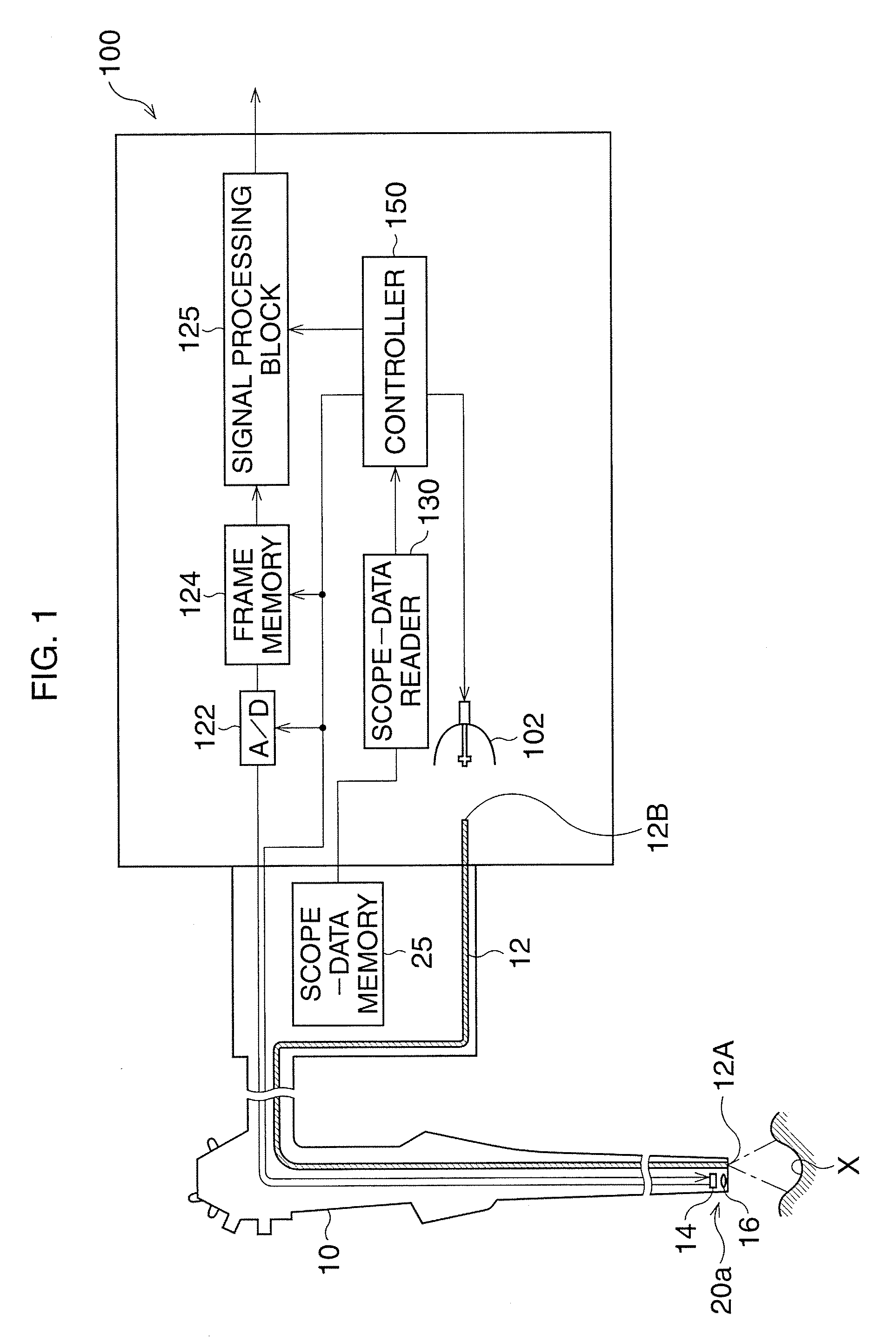
[0041]FIG. 1 is a block diagram showing an electronic endoscope system in one embodiment of this invention. The electronic endoscope system has a video-processor 100, a video-scope 10 that can be attached to or removed from the video-processor 100, and a monitor (not shown in the figures) that is connected to the video-processor 100.

[0042] The video-scope 10 has a light guide 12 that is composed of an optical fiber bundle and that is inserted into the video-scope 10. An output end 12A of the light guide 12 is disposed on a tip portion 20a of the video-scope 10, and an incident end 12B of the light guide 12 is disposed in the video-processor 100.

[0043] The video-processor 100 h...


PUM


Abstract

A device, for processing each pixel signal output from a solid-state imaging device, has a determination processor and an interpolation processor. Each pixel is defined as a center pixel of a k×k matrix. The interpolation processor presumes which pixels have the same color as one another in the k×k matrix, according to the plurality of pixel-array patterns, and conducts a pixel interpolation in each case of presumed color arrangement according to the plurality of pixel-array patterns, so as to generate signal groups of presumed interpolation signals of the center pixel. The determination processor determines a pixel-array pattern in the k×k matrix to be a pattern selected from the plurality of pixel-array patterns. One of the signal groups that is generated according to the determined pixel-array pattern is selected as interpolation signals of the center pixel.

Description

BACKGROUND OF THE INVENTION [0001] 1. Field of the Invention [0002] The present invention relates to an image signal processing device for processing pixel signals that are obtained by a single CCD system, and to a method of processing the pixel signals. [0003] 2. Description of the Related Art [0004] Conventionally, several color imaging systems including the single-CCD system, the 3-CCD system, and the frame sequential method are known. In particular, the single-CCD system is used in a household video camera and in an electronic endoscope because it can output three or four color signals while having simple structure. [0005] In the single-CCD system, a color filter array, which is composed of magenta (Mg), green (G), cyan (Cy), and yellow (Ye) color filters arranged in a mosaic array, is provided on a light-receiving surface of the CCD. On the CCD, the pixels having Mg, G, Cy, and Ye filters generate the Mg, G, Cy, and Ye color signals, respectively. [0006] The pixel data of each ...

Claims


Application Information

Patent Timeline
IPC IPC(8): H04N9/04
CPCG06T3/4015H04N9/045H04N2209/046H04N23/843H04N25/134
Inventor NAGAKURA, NAOKO
Owner HOYA CORP
Learn More