
Tunable micro-aspherical lens and manufacturing method thereof

a manufacturing method and micro-aspherical technology, applied in the field of tunable micro-aspherical lenses and a manufacturing method thereof, can solve the problems of inability to obtain adequate focus spot resolution provided by a general microlens, inability to resolve spherical aberration, and loss of weight and convenience, so as to eliminate spherical aberration

Inactive Publication Date: 2007-05-31
NATIONAL TSING HUA UNIVERSITY
View PDF5 Cites 24 Cited by
  • Summary
  • Abstract
  • Description
  • Claims
  • Application Information

AI Technical Summary

Benefits of technology

"The present invention provides a tunable micro-aspherical lens and a manufacturing method thereof. The lens uses two potential differences provided by two sets of electrodes to dynamically change a bottom area and a central height of a liquid polymer lens. This eliminates spherical aberration and allows the lens to self-assemble to a specific position. The lens can collimate a Fresnel diffraction fringe and form a micro optical device involving diffraction and refraction. The manufacturing method involves forming a lower electrode plate with a Fresnel diffraction fringe pattern, an insulation layer, and a hydrophobic pattern, and then sequentially adding an upper transparent electrode plate to control the curved surface of the liquid polymer lens. The lens can absorb an external energy to condense to form a solid micro-aspherical lens."

Problems solved by technology

If a traditional optical device is forced to meet the requirement of current portable products, its advantages, such as weight and convenience, will be lost.
However, an adequate focus spot resolution provided by a general microlens cannot be obtained due to spherical aberration, and in micro optical systems the issue of spherical aberration cannot be resolved by the combination of plural spherical lenses.
When the size of the lens shrinks down to a scale of a micro-system ranging from centimeters to sub micron, a delicate control method is required and the manufacturing process is time-consuming if a traditional machining process is used to manufacture a micro-aspherical lens.
Once the lens is fabricated by this method, with a fixed shape, it cannot subsequently be modulated to change its optical characteristic.
However, the tunable micro-aspherical lens with a pneumatic pump is not compatible to general optoelectronic products and the tunable range is limited to one dimension, resulting in spherical aberration at the edge.
The modulation of a lens by electric field is proved to be feasible by commercialization of Philips′ variable-focus system; however, the tunable range thereof is limited to one dimension.

Method used


Image

  • Tunable micro-aspherical lens and manufacturing method thereof
  • Tunable micro-aspherical lens and manufacturing method thereof
  • Tunable micro-aspherical lens and manufacturing method thereof

Examples


Embodiment Construction

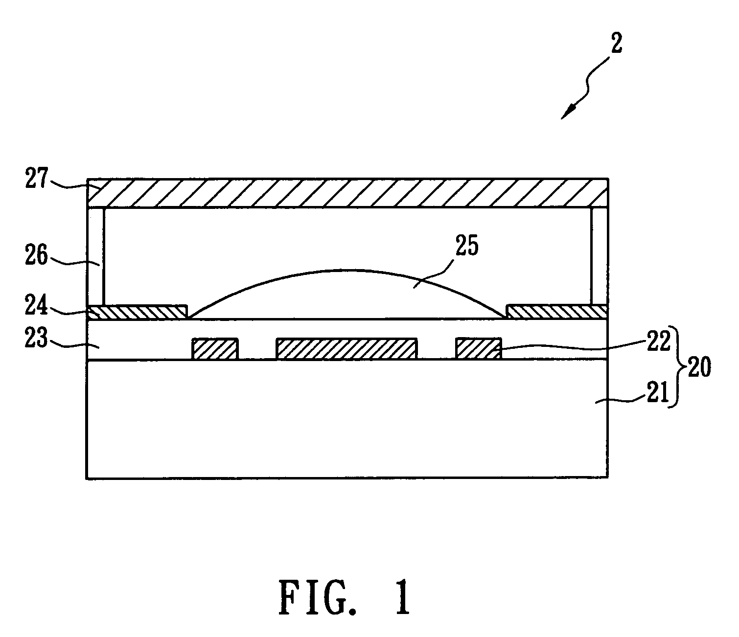
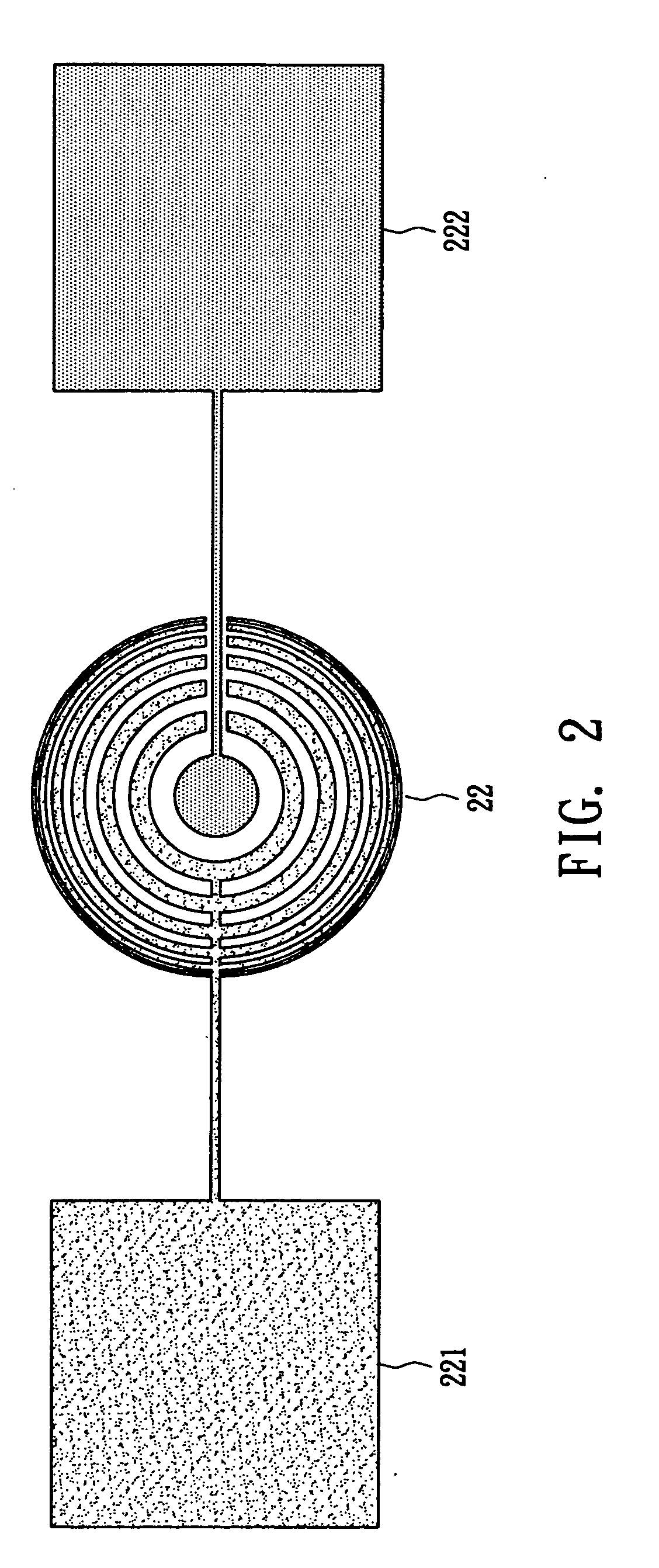
[0023]FIG. 1 illustrates the cross-section view of one embodiment of the tunable micro-aspherical lens 2 of the present invention. The tunable micro-aspherical lens 2 comprises a transparent substrate 21, a Fresnel diffraction fringe pattern 22, an insulation layer 23, a hydrophobic pattern 24, a liquid polymer lens 25, a spacer 26 and an upper transparent electrode plate 27. The transparent substrate 21 and the Fresnel diffraction fringe pattern make up a lower electrode plate 20. When an incident light passes through the transparent substrate 21, it is pre-focused and collimated by the Fresnel diffraction fringe pattern 22 first and then refracted by the liquid polymer lens 25. Finally, it is focused after transmitting the upper transparent electrode plate 27.

[0024] The manufacturing method of a tunable micro-aspherical lens of the present invention is described in detail below. Step one is to form a lower electrode plate 20 comprising a Fresnel diffraction fringe pattern 22 that...


PUM


Abstract

A tunable micro-aspherical lens is disclosed, which employs two potential differences provided by two sets of electrodes to dynamically change the bottom area and the central height of the liquid polymer lens. The tunable micro-aspherical lens includes a tunable lens, a lower electrode plate, a hydrophobic pattern, an insulation layer and an upper transparent electrode plate. Also, a manufacturing method of a tunable micro-aspherical lens is disclosed, which includes forming a lower electrode plate, forming an insulation layer, determining a position of the tunable lens, controlling the bottom area and the central height of the tunable lens. The tunable micro-aspherical lens of the present invention eliminates spherical aberration and improves the focus spot resolution to shrink the focus spot and thus to provide better optical quality.

Description

RELATED U.S. APPLICATIONS [0001] Not applicable. STATEMENT REGARDING FEDERALLY SPONSORED RESEARCH OR DEVELOPMENT [0002] Not applicable. REFERENCE TO MICROFICHE APPENDIX [0003] Not applicable. [0004] 1. Field of the Invention [0005] The present invention relates to a tunable micro-aspherical lens and a manufacturing method thereof, and more particularly, to a tunable micro-aspherical lens and a manufacturing method thereof based on two-dimensional electrostatic modulation technology, which is especially suitable for optical fiber communication, display, biomedical diagnosis and optical storage equipment. [0006] 2. Background of the Invention [0007] Recently, there has been rapid growth in the use of various optoelectronic products. Optoelectronic products require an optical interface to communicate between the human and the optoelectronic product or require an optical device installed within the optoelectronic product such as an LCD display and a digital camera. Due to decreasing siz...

Claims


Application Information

Patent Timeline
Patent Type & Authority Applications(United States)
IPC IPC(8): G02B27/10
CPCG02B3/14G02B26/005
Inventor TSENG, FAN GANGCHEN, CHANG WEI
Owner NATIONAL TSING HUA UNIVERSITY
Learn More