
Image processor and camera system

a technology of image processing and camera system, applied in the field of image processing, can solve the problems of distortion of an image of a subject and similar distortion

Active Publication Date: 2007-05-31
MEGACHIPS
View PDF5 Cites 68 Cited by
  • Summary
  • Abstract
  • Description
  • Claims
  • Application Information

AI Technical Summary

Benefits of technology

The present invention provides a technique for appropriately correcting image distortion caused by rolling shutter type exposure in a camera system. The invention includes a motion detecting part and a moving region correcting part. The motion detecting part detects motion in a plurality of frame images captured by rolling shutter type exposure and obtains motion vectors and image-capturing time intervals. The moving region correcting part uses the motion vectors, image-capturing time intervals, exposure starting time differences, and exposure-start sequence information to correct the moving region in the to-be-corrected frame image. This results in a composite frame image with reduced image distortion. The invention also includes an exposure-time determining part and a frame-image generating part. The exposure-time determining part determines the exposure time period by dividing the exposure time period by the number of frame images. The frame-image generating part generates a composite frame image with the corrected moving region by shifting the pixels in the moving region of the to-be-corrected frame image in the opposite direction of the motion vector, exposure starting time differences, and exposure-start sequence information. The invention helps reduce image distortion caused by rolling shutter type exposure and improves image quality in a camera system.

Problems solved by technology

Since the rolling-shutter-type image capturing apparatus provides a different exposure starting time for each pixel or each line of pixels in one frame image as described above, capturing an image of a moving subject with that image capturing apparatus may cause a distortion in an image of that subject.
Even when capturing a stationary subject with the rolling-shutter-type image capturing apparatus, a distortion may similarly occur because of hand shake of a user.

Method used


Image

  • Image processor and camera system
  • Image processor and camera system
  • Image processor and camera system

Examples


Embodiment Construction

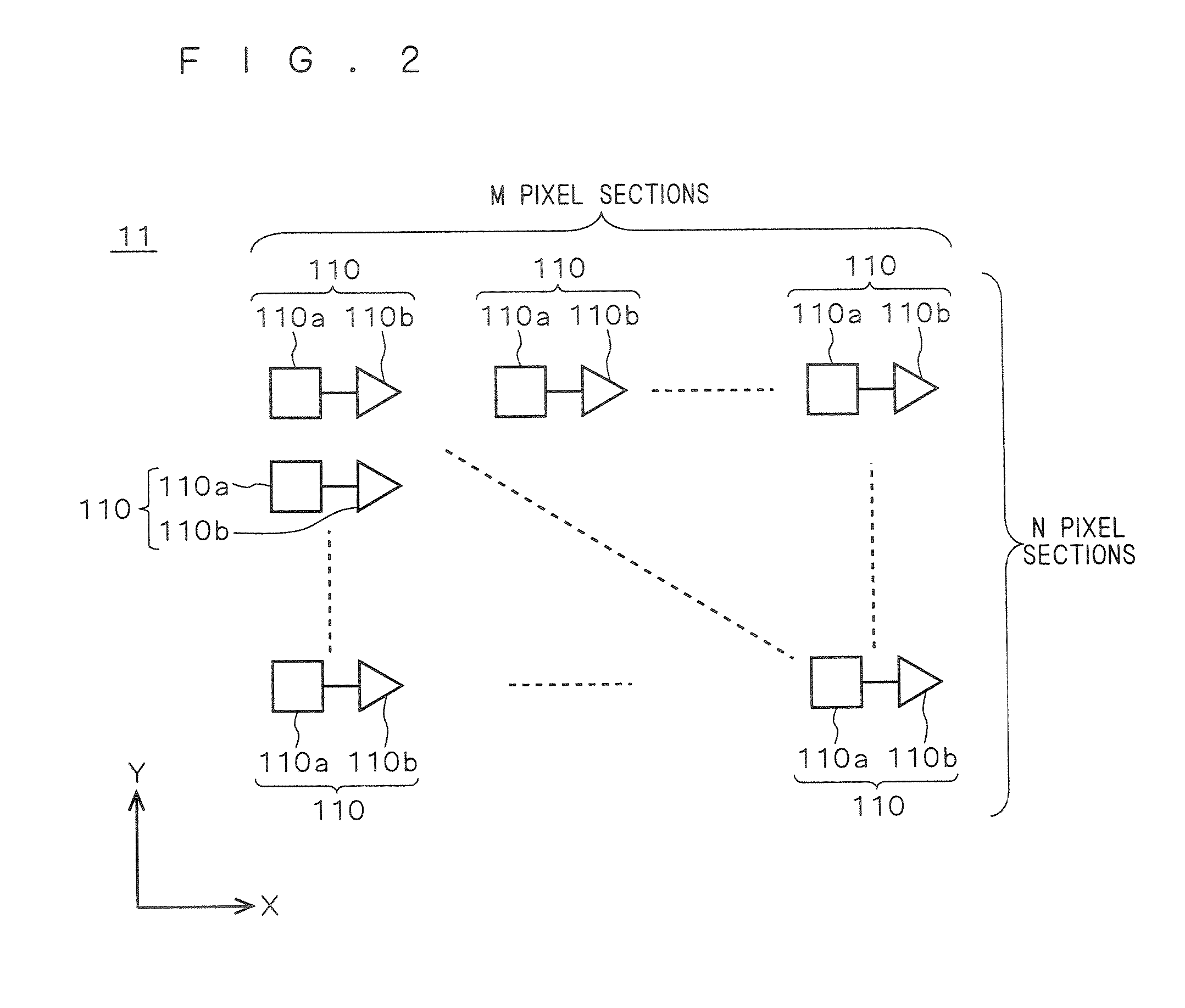
[0042]FIG. 1 is a block diagram showing the configuration of a camera system according to a preferred embodiment of the present invention. The camera system according to the present embodiment is a digital still camera, for example, for capturing images by the rolling shutter type exposure. As shown in FIG. 1, the camera system includes an image capturing apparatus 1 for capturing images, an image processor 2 for carrying out image processing on images captured by the image capturing apparatus 1, and a display device 3 for displaying images processed by the image processor 2.

[0043] The image capturing apparatus 1 has a lens unit 10, a CMOS sensor 11, a CMOS sensor driving circuit 12, a timing generator 13 and an A / D converter 14. The CMOS sensor 11 converts light incident from a subject through the lens unit 10 into an electric signal to capture an image and outputs the captured image as an analog image signal AIS. The timing generator 13 generates and outputs a timing signal TS, a...


PUM


Abstract

A motion detecting part detects moving regions in a plurality of frame images captured by rolling shutter type exposure, and obtains a motion vector of the moving regions. A moving region correcting part corrects the moving region in a to-be-corrected frame image of the plurality of frame images on the basis of the motion vector, information on an image-capturing time interval between the plurality of frame images, information on an exposure starting time difference resulting from the difference in position in one frame image caused by the rolling shutter type exposure and information on an exposure start sequence depending on the position in one frame image captured by the rolling shutter type exposure.

Description

BACKGROUND OF THE INVENTION [0001] 1. Field of the Invention [0002] The present invention relates to an image processor for carrying out image processing on an image captured by rolling shutter type exposure, and also relates to a camera system equipped with such image processor. [0003] 2. Description of the Background Art [0004] Conventionally known exposure techniques for capturing images are of global shutter type and rolling shutter type (also called “focal plane shutter type”). A global-shutter-type image capturing apparatus represented by an image capturing apparatus equipped with CCD (Charge Coupled Device) sensors provides almost the same exposure time period and exposure starting time for each pixel in one frame image. In contrast, a rolling-shutter-type image capturing apparatus represented by an image capturing apparatus equipped with CMOS sensors provides the same exposure time period but different exposure starting time for each pixel or each line of pixels in one frame...

Claims


Application Information

Patent Timeline
Patent Type & Authority Applications(United States)
IPC IPC(8): H04N5/235H04N23/40
CPCH04N5/23248H04N5/2329H04N5/2621H04N5/272H04N23/689H04N23/68
Inventor SASAKI, GENNARA, YUSUKE
Owner MEGACHIPS
Learn More