Eureka AIR delivers breakthrough ideas for toughest innovation challenges, trusted by R&D personnel around the world.

Method and system for treating chemical waste

a chemical waste and chemical technology, applied in the field of chemical production lines, can solve the problems of large quantities of harmful chemicals being stored each year around the world, high cost of disposing of industrial chemical waste, etc., and achieve the effect of rapid reduction of the temperature of the mixtur

Inactive Publication Date: 2007-05-24
E S T ECOLOGICAL SYST
View PDF16 Cites 4 Cited by
  • Summary
  • Abstract
  • Description
  • Claims
  • Application Information

AI Technical Summary

Benefits of technology

The invention is a system and method for neutralizing fluid chemical waste products that result from a chemical production process. The system includes a pyrolysis / reaction chamber with plasma torches, a pre-pyrolysis subsystem, a post-pyrolysis subsystem, and a control unit. The system can be located at the end of the production line or temporarily stored and then moved around. The method involves activating the plasma torches to produce a plasma stream, activating the pre-pyrolysis subsystem to create droplets that contact the plasma stream, creating predetermined conditions for the droplets to dissociate molecules of waste into atoms or ions, and activating the post-pyrolysis subsystem to neutralize the recombination products. The system and method can be used to neutralize various types of fluid chemical waste products, such as liquids, gases, or solids dissolved in a solvent.

Problems solved by technology

Disposal of this industrial chemical waste is very expensive since it requires special packaging materials, handling equipment, and storage areas.
More importantly the present methods results in large quantities of harmful chemicals being stored each year around the world.

Method used


Image

  • Method and system for treating chemical waste
  • Method and system for treating chemical waste
  • Method and system for treating chemical waste

Examples


Embodiment Construction

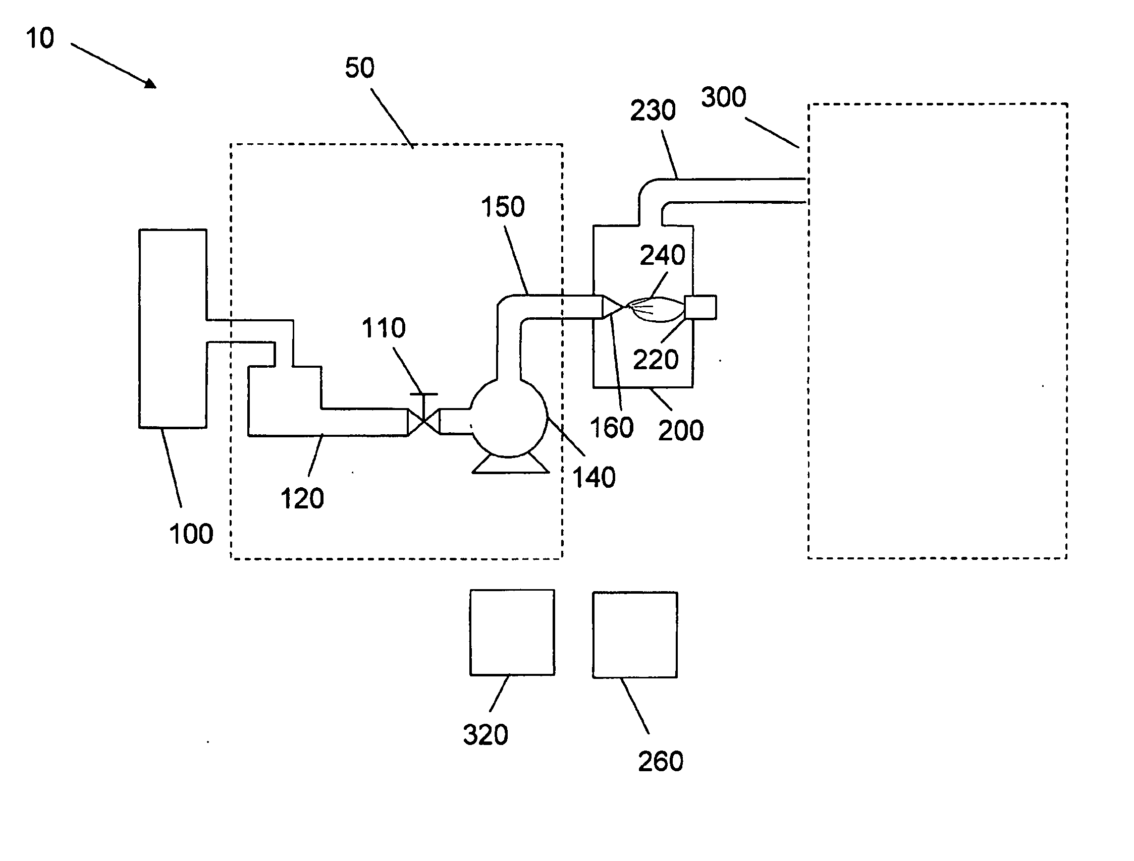
[0040] In FIG. 1 is schematically shown the system 10 for treating chemical waste according to the present invention. Block 100 represents a conventional industrial production line used to produce a particular chemical. The production of the desired product typically is carried out on a continuous processing line. The entire process may be a “one pot” process or may involve many steps involving separation of intermediate products from secondary products or waste, addition of more raw material, and provision of the proper conditions for the production of the next intermediate product. Each step is typically accompanied by the production of waste products, which must eventually be disposed of and the process continues until the final desired product is collected at the end of the production line.

[0041] Container 120 represents a collection and / or temporary storage facility at the end of the production line into which all of the accumulated waste is collected. This representation is s...


PUM

PropertyMeasurementUnit
operating temperaturesaaaaaaaaaa
temperatureaaaaaaaaaa

Abstract

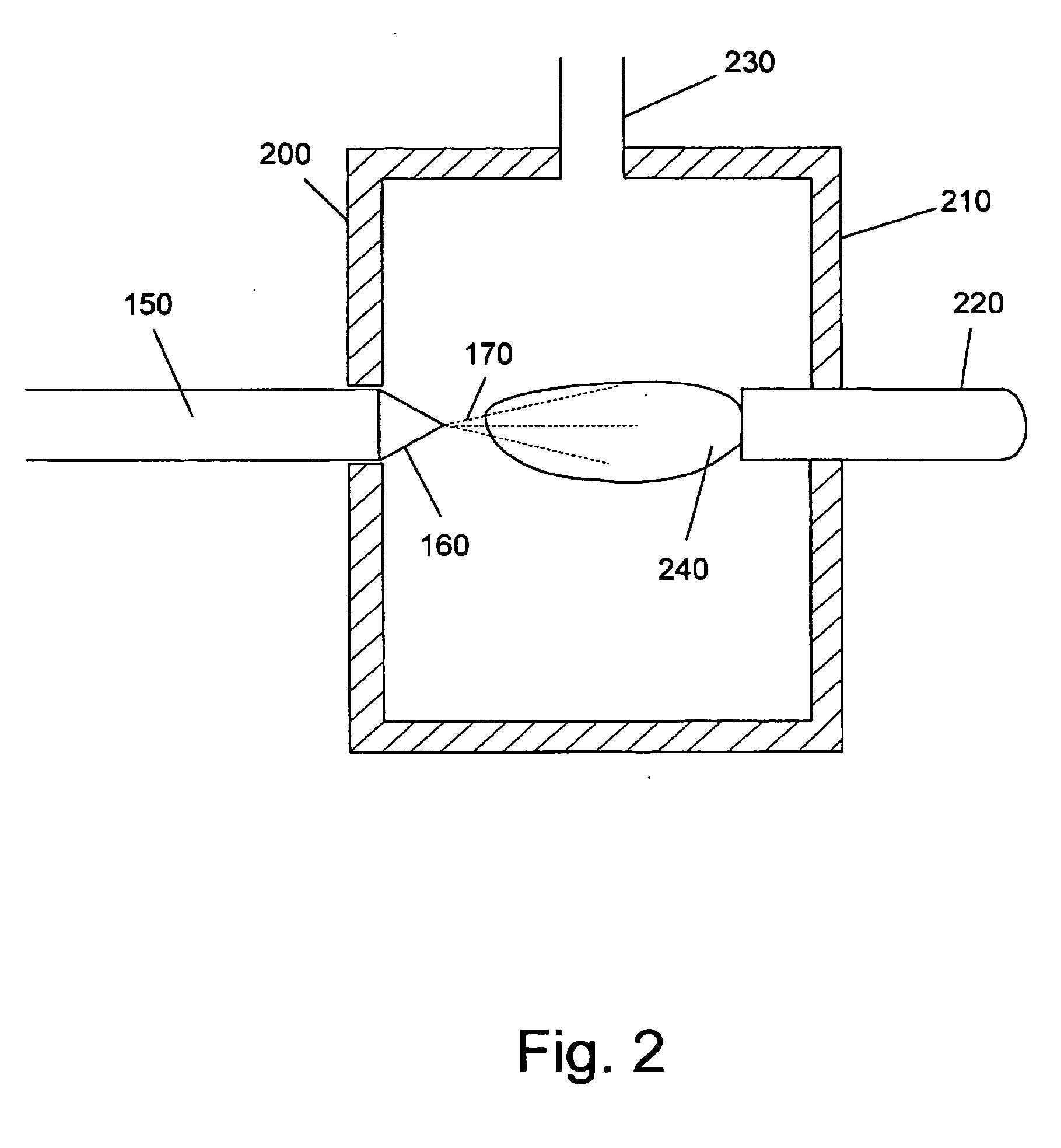
The invention is a system and method for neutralizing fluid chemical waste products that result from a chemical production process and are collected from the production line. The invention comprises a pyrolysis / reaction chamber into which the fluid chemical waste is pumped through an atomizer. The jet of small droplets of liquid waste that is formed by the atomizer effectively contacts the plasma stream created by a plasma torch. When the droplets contact the plasma stream the molecules of the waste from which the droplets are composed are dissociated into atoms and / or ions. These atoms and ions move out of the immediate region of the plasma stream and recombine to form a mixture of product gases which exits the chamber. The product gases then enter a post-pyrolysis subsystem, which is designed to neutralize and / or collect the components comprising the mixture of product gases.

Description

FIELD OF THE INVENTION [0001] The present invention is related to the field of chemical production lines. In particular the invention relates to providing a solution to the problem of safely disposing of the chemical waste products that result from the production process and are collected from the production line. BACKGROUND OF THE INVENTION [0002] Many processes used in the chemical industry produce chemical waste, which at room temperature may be gaseous, liquid, or solid. There are many known methods to treat and discard gaseous and liquid waste. Treatment of gaseous waste, for obvious reasons is generally carried out at the point of their creation. Liquid waste can sometimes be carried out in the production facility, but very often the waste products are stored in containers and transported to another site for treatment. Waste that solidifies when held at ambient temperature (hereinafter solid waste) is also usually packed in containers that are then transported to special facil...

Claims


Application Information

Patent Timeline
Patent Type & Authority Applications(United States)
IPC IPC(8): C10B51/00
CPCB01D2259/818B01J19/08B01J19/088B01J2219/0801B01J2219/0816B01J2219/0875B01J2219/0877B01J2219/089B01J2219/0898C10G1/02C10G2300/1003
Inventor SIMON, YEHUDA YURI
Owner E S T ECOLOGICAL SYST
Why Eureka
Eureka Blog
Learn More