
Tire pressure gauge with sensor support

a technology of pressure gauge and sensor, which is applied in the direction of vehicle tyre testing, instruments, roads, etc., can solve the problems of adverse effects on vehicle handling, adverse effects on fuel economy, and increase in tire wear rates, so as to maintain proper calibration and function.

Inactive Publication Date: 2007-05-24
CREATIVE AUTO RESOURCES
View PDF30 Cites 15 Cited by
  • Summary
  • Abstract
  • Description
  • Claims
  • Application Information

AI Technical Summary

Benefits of technology

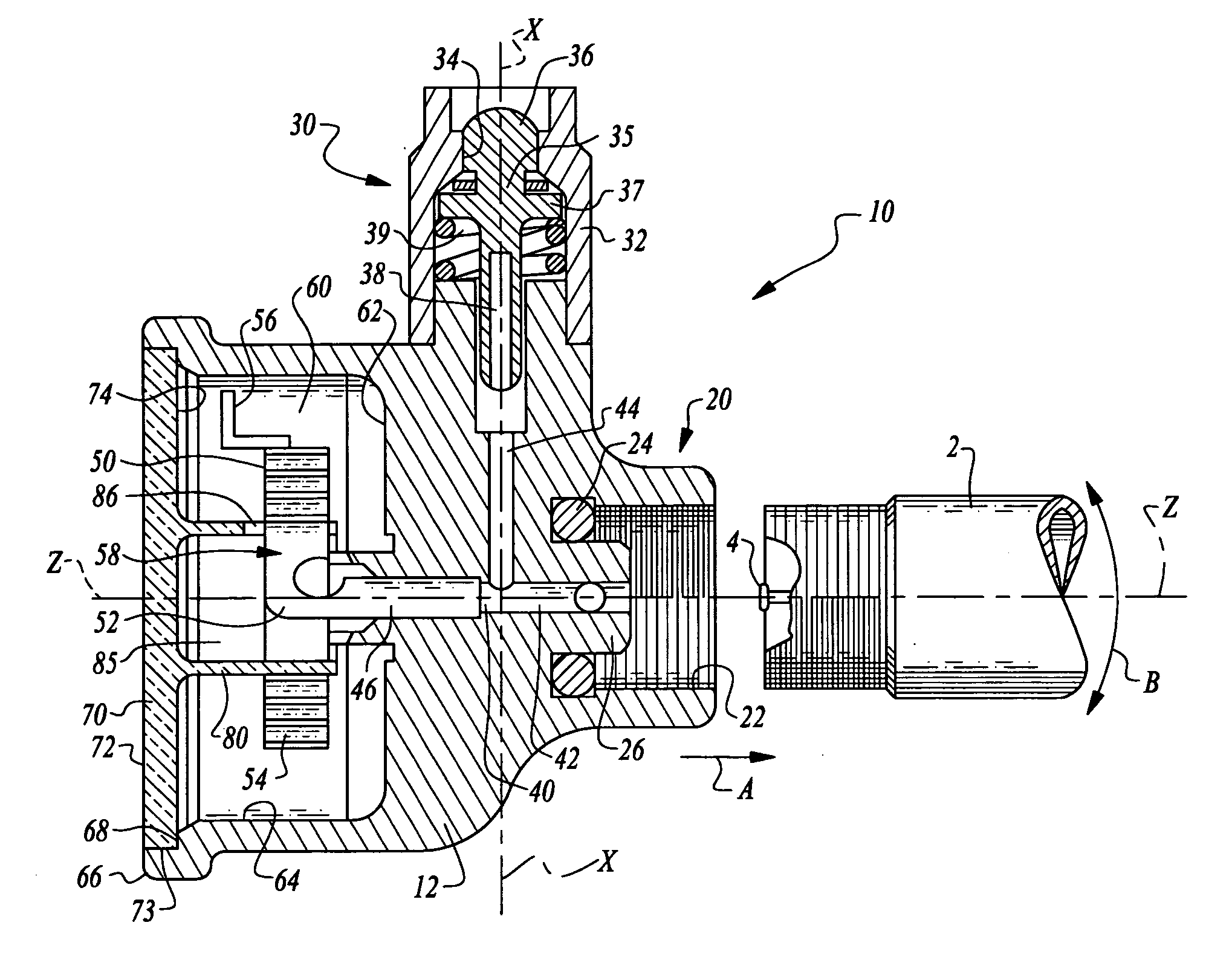
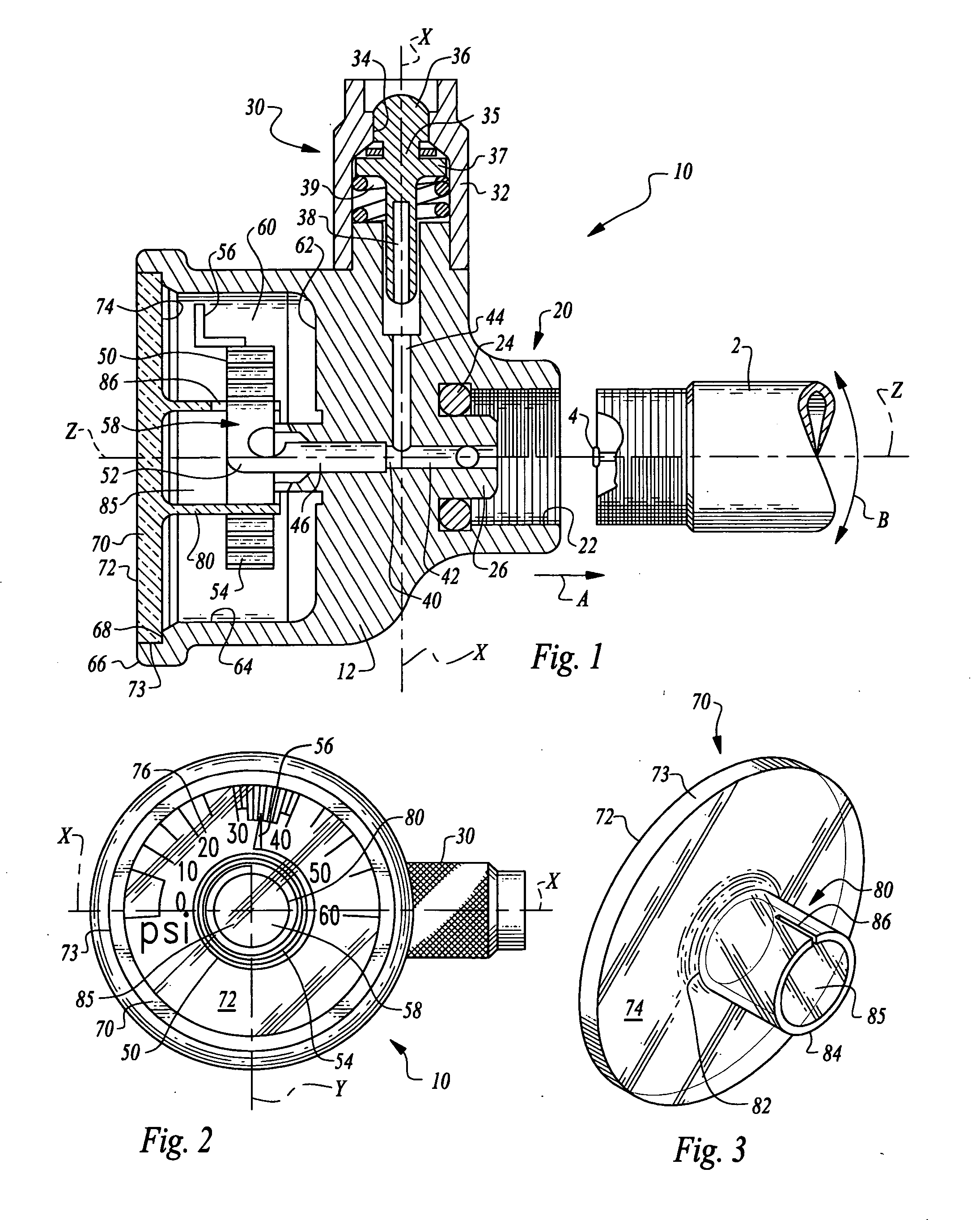
[0014] The Bourdon tube preferably resides within a sensor chamber covered and typically sealed by a lens and with indicia either upon the lens or a portion of the sensor chamber such that a sensor tip on the Bourdon tube can be aligned with the indicia to read the pressure contained within the compressed fluid reservoir associated with the valve stem. Some form of support surface, such as a shroud, is located within the sensor chamber and adjacent the Bourdon tube, and particularly a central opening of the Bourdon tube. This support surface keeps the Bourdon tube from being bent laterally when the entire gauge, including the Bourdon tube, is experiencing centrifugal forces or other forces associated with the compressed fluid reservoir (such as a tire) spinning at a high rate of speed, encountering bumps, or otherwise experiencing extreme forces. This support surface minimizes an amount of bending and associated stress and strain encountered by the Bourdon tube, keeping this stress and strain within allowable limits so that the Bourdon tube remains in proper calibration and continues to maintain proper function. In particular, the Bourdon tube can be loaded in a manner which causes unwinding of a coil of the Bourdon tube or tightening of the coil of the Bourdon tube (depending on the direction of rotation of the valve stem and the direction of spiral of the coil of the Bourdon tube). With this invention, the shroud or other support surface provides a solid and uniform support against which the Bourdon tube coil can tighten without damage or de-calibration, with the direction of spiral properly selected to avoid unwinding. OBJECTS OF THE INVENTION
[0015] Accordingly, a primary object of the present invention is to provide a tire pressure gauge which can remain mounted upon a tire during operation of the tire.
[0016] Another object of the present invention is to provide a tire pressure gauge which resists distortion or other damage when experiencing high centrifugal force environments and other high load environments.
[0017] Another object of the present invention is to provide a tire pressure gauge including a Bourdon tube and which keeps the Bourdon tube from becoming damaged even when the gauge remains on the tire during operation of the tire.

Problems solved by technology

If tire pressure is not maintained, fuel economy is adversely affected and rates of tire wear increase.
Additionally, handling of the vehicle can be adversely affected and the potential for abrupt failure of the tire is increased.
One of the difficulties encountered in such regular tire pressure monitoring is that a significant amount of time is associated with monitoring tire pressure.
On a vehicle with multiple tires, this basic routine can be significantly time consuming, decreasing the likelihood that tire pressure monitoring will occur on a sufficiently frequent basis.
Compounding this difficulty is the inconvenience encountered when tire pressure is low and air needs to be added to the tire.
While this solves a portion of the problem, the difficulty associated with adding air to the tire is not alleviated.
The tire pressure gauges taught by LaSalle and Hunt are not entirely satisfactory.
To accommodate this fill port passing through a center of the Bourdon tube, a customized Bourdon tube is required which significantly complicates the manufacture of the gauge taught by LaSalle.
Also, reading the pressure indicated by the Bourdon tube is made more difficult by the presence of a valve core in a middle of a face of the gauge.
However, the spiraling Bourdon tube is not fully supported for the extreme operating environment experienced when the Hunt gauge remains mounted upon the tire, and as the tire is rotating at high speed, such as when the vehicle is in operation.
These rotational forces impart a high degree of centrifugal force upon the Bourdon tube, tending to exceed an elastic limit of the materials and / or induce creep into the materials from which the Bourdon tube is formed, and potentially bringing the Bourdon tube out of proper calibration.
The Bourdon tube is particularly susceptible to damage in that it must purposefully be made of sufficiently thin material to allow it to flex in response to pressure changes.
Thus, over time the gauge taught by Hunt has a potential to become less accurate.

Method used


Image

  • Tire pressure gauge with sensor support
  • Tire pressure gauge with sensor support
  • Tire pressure gauge with sensor support

Examples


Embodiment Construction

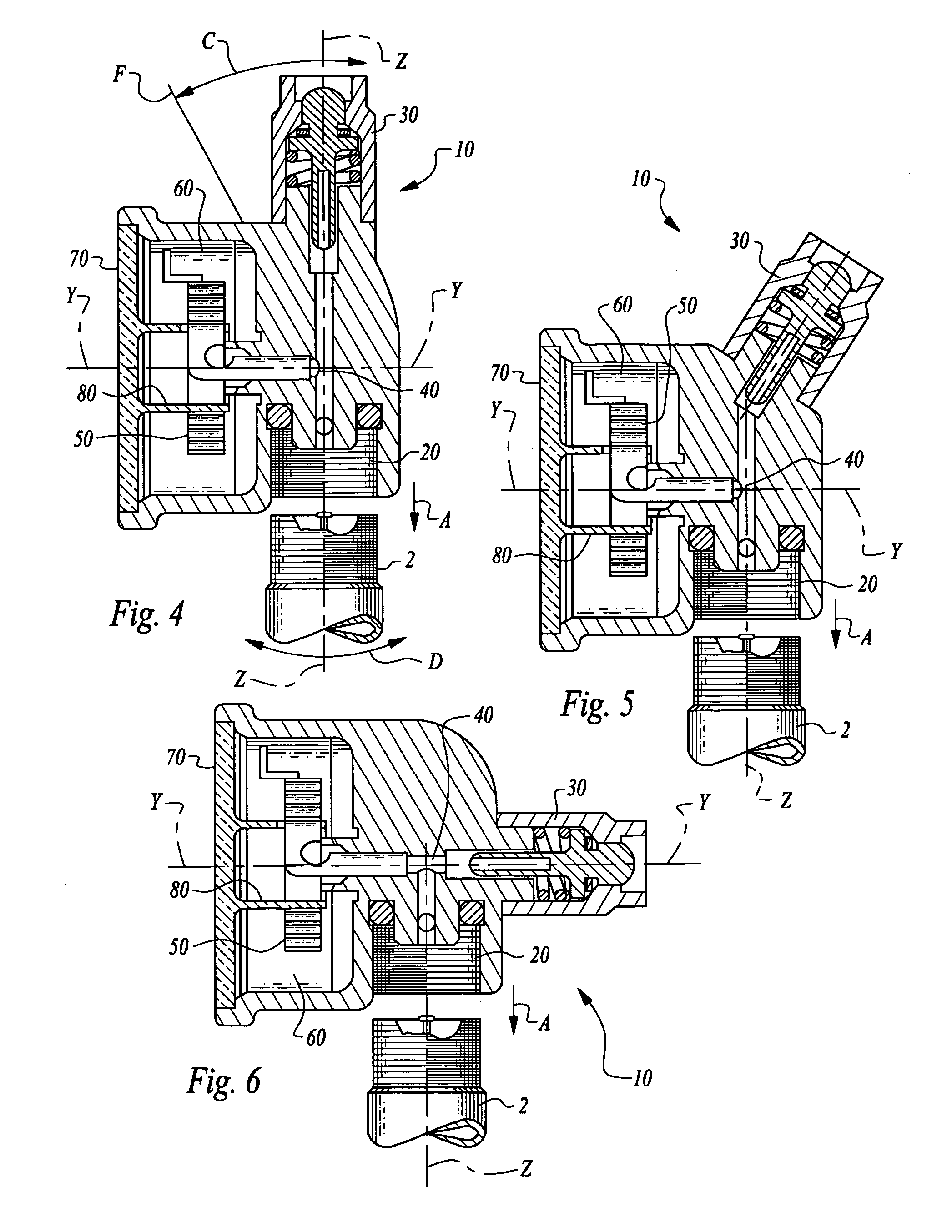
[0027] Referring to the drawings, wherein like reference numerals represent like parts throughout the various drawing figures, reference numeral 10 is directed to a gauge (FIGS. 1 and 2) which is particularly configured to measure pressure, and particularly the pressure within tires. The gauge 10 is configured to be mountable to a valve stem 2 of the tire with the gauge capable of remaining upon the valve stem 2 during operation of the tire without the gauge experiencing permanent damage due to the forces associated with rapid rotation and other forces encountered by a tire during vehicle operation.

[0028] In essence, and with particular reference to FIG. 1, basic details of the gauge 10 of this invention are described according to a preferred embodiment. The gauge 10 includes a receiver 20 which is particularly configured to be mountable to the valve stem 2 of a compressed fluid reservoir such as a tire. A valve core 30 is optionally but preferably also included on the gauge 10. Th...


PUM


Abstract

A pressure gauge is provided for monitoring pressure within a reservoir, such as air within a vehicle tire. The gauge is particularly configured to allow it to remain upon a valve stem of the tire even when the tire is in operation. A receiver of the gauge can be coupled to the valve stem. A valve core is preferably provided through which air can pass from a compressed air source, so that the tire can be filled without removing the gauge. A Bourdon tube is located within a sensor chamber and measures pressure within the reservoir. A shroud or other support surface is located adjacent a central opening of the Bourdon tube so that the Bourdon tube is supported sufficiently to avoid damage from forces including centrifugal forces encountered when the tire is spinning and the gauge is mounted on the valve stem of the tire.

Description

CROSS-REFERENCE TO RELATED APPLICATIONS [0001] This application claims benefit under Title 35, United States Code § 119(e) of U. S. Provisional Application No. 60 / 645,278 filed on Jan. 18, 2005. FIELD OF THE INVENTION [0002] The following invention relates to pressure gauges, and particularly pressure gauges for measuring tire pressure. More specifically, this invention relates to tire pressure gauges which are configured to remain mounted upon a valve stem of a tire while the tire is in operation on the vehicle, with a pressure sensing Bourdon tube supported so that it does not become de-calibrated or otherwise damaged by the forces associated with operation of the tire. BACKGROUND OF THE INVENTION [0003] One important criteria for safely operating a motor vehicle is the maintenance of proper pressure within tires of the vehicle. If tire pressure is not maintained, fuel economy is adversely affected and rates of tire wear increase. Additionally, handling of the vehicle can be adver...

Claims


Application Information

Patent Timeline
IPC IPC(8): G01L7/04
CPCB60C23/0496G01L7/043G01L17/00
Inventor RUTHERFORD, ROBERT B.LEVENSON, MIKE
Owner CREATIVE AUTO RESOURCES
Learn More