
Self-backhaul method and apparatus in wireless communication networks

a wireless communication network and self-backhaul technology, applied in the field of wireless communication networks, can solve the problems of low network capacity demand, low initial subscribers, and low network construction cost, and achieve the effect of significantly improving the ability of wireless return transmission and reducing investment and operation costs

Inactive Publication Date: 2007-05-17
ALCATEL LUCENT SAS
View PDF19 Cites 47 Cited by
  • Summary
  • Abstract
  • Description
  • Claims
  • Application Information

AI Technical Summary

Benefits of technology

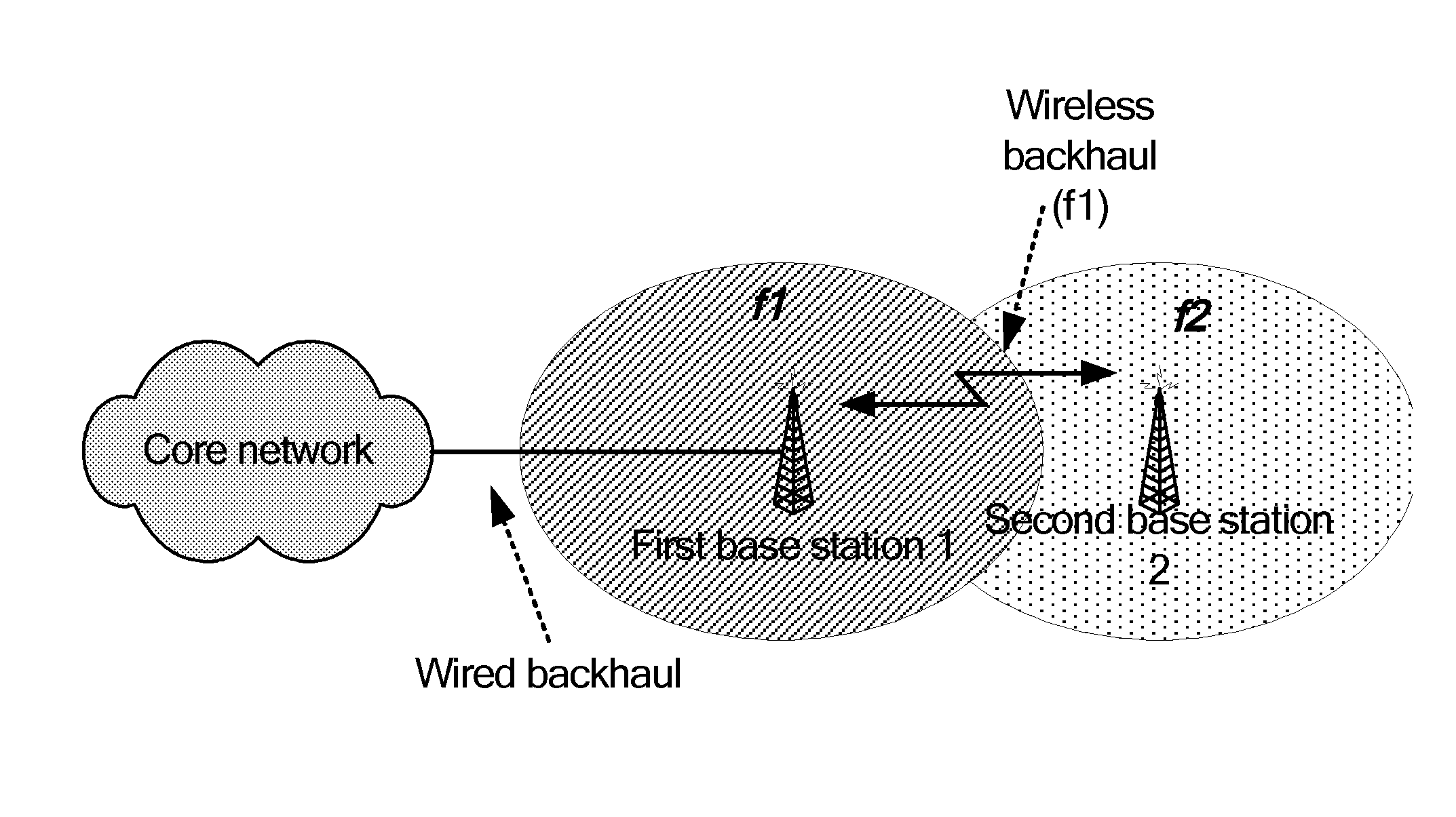
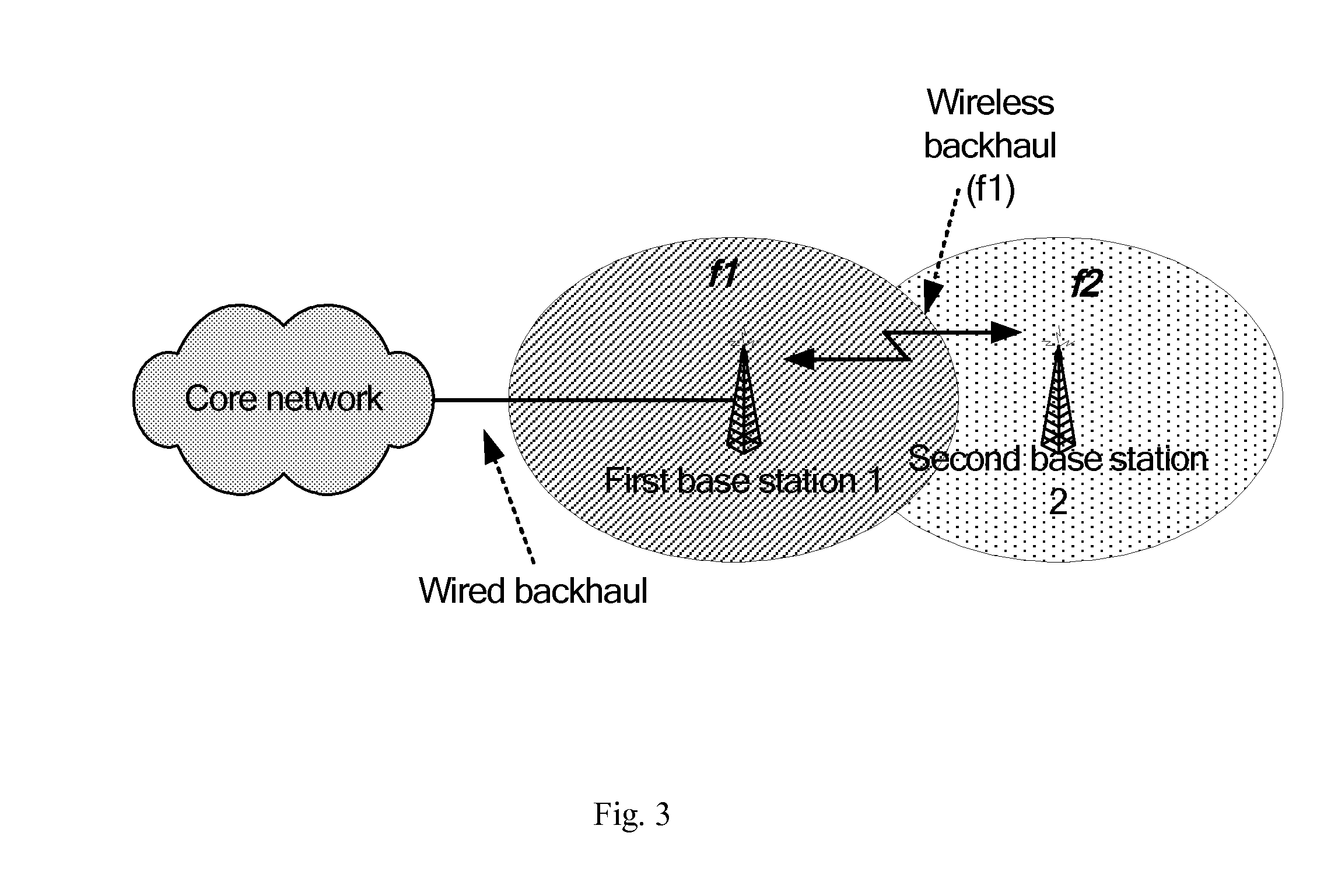
[0015] According to a first aspect of the present invention, provided is a method of implementing wireless traffic backhaul between a first base station and a second base station in a wireless communication network, which comprises the following steps: a) forming an uplink backhaul channel and a downlink backhaul channel between said first base station and said second base station by using timeslots of base stations' own; b) implementing uplink and downlink traffic backhaul between said first base station and said second base station by using said uplink backhaul channel and said downlink backhaul channel. Preferably, step a) is offsetting the frame start time of the second base station for a period of time in relation to the frame of the first base station, so as to form an uplink backhaul channel and a downlink backhaul channel between said first base station and said second base station.
[0016] According to a second aspect of the present invention, provided is a base station of implementing wireless backhaul in a wireless communication network, said base station being the master base station of a second base station and comprising transceiver means for receiving from and sending to a subscriber station information, wherein said transceiver means is further used for receiving from and sending to the second base station backhaul information over uplink and downlink backhaul channels between said base station and said second base station that are formed by using timeslots of base stations' own. Preferably, said uplink and downlink backhaul channels are formed by offsetting the frame start time of the second base station for a period of time in relation to the frame of said master base station.
[0019] Compared with the prior arts, the technical solution of the present invention achieves wireless communication between base stations by using radio resources of base stations' own, and wireless communication networks of the prior arts do not have such a function. During network deployment by using the present invention, the same kind of equipment is used without adding new hardware equipment or applying for different frequency resources, so that users' investment and operation costs are greatly reduced. Moreover, since the strong wireless transmission capability which a base station itself has is used in wireless backhaul traffic, the wireless return transmission capability can be significantly improved.

Problems solved by technology

There, the number of initial subscribers is very limited, the type of service applications is simplistic, and the demand for network capacity is relatively small.
A critical problem for achieving the above large-scale application of wireless communication networks lies in how to achieve fast networking and reduce network construction costs.
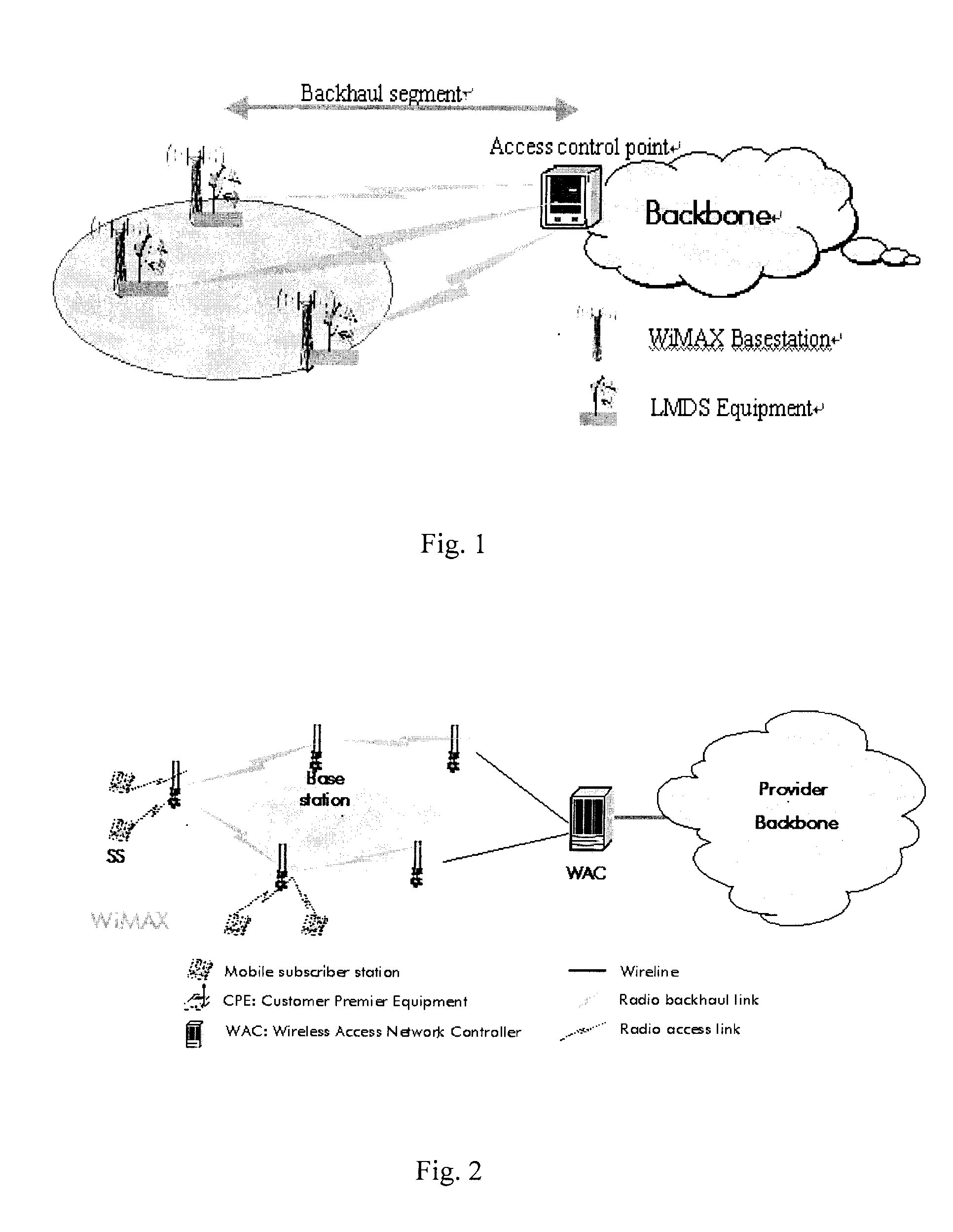
As illustrated in FIG. 1, although the combination of WiMAX and LMDS techniques can support WiMAX wireless return network deployment, costs of the network construction investment and daily operation and maintenance are very high, because two kinds of equipment need to be used during network deployment.
In practical applications, frequency resources are usually auctions off to operators by the government, and it is hard for most operators to have such abundant frequency resources in specific areas.
Additionally, after years of development, the LMDS technique still does not have a global unified standard, and the interworking of products by different manufacturers is extremely difficult.
Furthermore, LMDS operates in high band and must work in the LOS (line-of-sight) mode, which also restricts its application range.
Thus, costs of the network construction investment and daily operation and maintenance will still increase.

Method used


Image

  • Self-backhaul method and apparatus in wireless communication networks
  • Self-backhaul method and apparatus in wireless communication networks
  • Self-backhaul method and apparatus in wireless communication networks

Examples


Embodiment Construction

[0031] According to an embodiment of the present invention, a complete frame, such as a complete IEEE 802.16 frame, of a base station in a wireless communication network can be divided into two parts. Part of the timeslots is used for the wireless backhaul functionality, and the other part is still used for the ordinary user access functionality (e.g. the WiMAX user access functionality). Two base stations transferring backhaul traffic asynchronously perform the receiving and transmitting functionality in time slices corresponding to receiving and transmitting timeslots of the master and slave base stations. In a backhaul timeslot, one base station is in a transmitting state while the other one is in a receiving state. In a user access timeslot, the two base stations perform reception and transmission at the same time. The mater and slaver base stations communicate with their respective subscriber stations. Base stations within the wireless communication networks are classified as m...


PUM


Abstract

The present invention relates to a wireless self-backhaul technique in a wireless communication network, especially in a WiMAX network, which implements wireless backhaul between base stations by using radio resources (frequency, sub-band or timeslot) of base stations' own. More specifically, uplink and downlink backhaul channels are formed between a master base station and a slaver base station using base stations' inherent resources and through offsetting the frame start time of the slaver base station for a period of time in relation to the master base station. The slaver base station operates in base station mode during local user access and operates in subscriber station mode during implementing wireless backhaul traffic with the master base station. Therefore, the slaver base station needs to switch between these two operating modes.

Description

CROSS-REFERENCE TO RELATED APPLICATION(S) [0001] This application is based on the Chinese Patent Application No. 200510110325.6 filed on Nov. 11, 2005, the disclosure of which is hereby incorporated by reference. FIELD OF THE INVENTION [0002] The present invention relates to wireless communication networks, and particularly to the self-backhaul technique in wireless communication networks. BACKGROUND OF THE INVENTION [0003] At the beginning of deployment, wireless communication networks, like WiMAX networks (world interoperability microwave access, a wireless metropolitan network technique based on IEEE 802.16 serial standards), are mainly directed to developing countries, outskirts and areas where network infrastructure is not very perfect. There, the number of initial subscribers is very limited, the type of service applications is simplistic, and the demand for network capacity is relatively small. At this point, the key to success lies in how to use the low-cost network coverage...

Claims


Application Information

Patent Timeline
IPC IPC(8): H04B7/216H04W16/26H04W84/22H04W92/20
CPCH04W16/26H04W84/22H04W92/20
Inventor JIN, SHANLIU, JIMINLENG, XIAOBINGSHEN, GANG
Owner ALCATEL LUCENT SAS
Learn More