Apparatus and method of non-sampling-based Q-factor measuring

Active Publication Date: 2007-05-17
IND TECH RES INST
View PDF5 Cites 7 Cited by
  • Summary
  • Abstract
  • Description
  • Claims
  • Application Information

AI Technical Summary

Benefits of technology

[0014] To overcome the drawback of the foregoing conventional optical signal measurement processes with sampling techniques, the present invention provides a non-sampling-based Q-factor measuring apparatus and method. With a power conversion module, the present invention converts the power variation of input optical signals in time domain into the variation in a non-time domain and accomplishes the same result from the signal sampling mechanism. Via an equivalent non-time variant analytical mechanism, the mean and standard deviation of the power variation for the input optical signals at levels 1 and 0 can be obtained, and the Q-factor for the input optical signals is easily measured.
[0018] In the second embodiment of the present invention, the optical signal power variation in time domain is converted into different output ports of an optical device. Accordingly, the non-sampling-based Q-factor measuring apparatus is accomplished by a nonlinear directional coupler connected to a low frequency photo detector. Due to Kerr electro-optical effect, input optical signals with higher power exit via one of the output port, while input optical signals with lower power exit via another output port. Input optical signals at levels of 1 and 0 can thus be separated. By calculating the respective statistical mean and standard deviation values, the Q-factor can be easily measured.
[0021] Through the non-sampling-based mechanism in the embodiments of the present invention, the Q-factor measuring can be easily accomplished without the drawbacks / restrictions in the conventional optical signal sampling mechanism.

Problems solved by technology

The detection for the bit error rate requires more complicated equipment, and the time required for detecting a lower BER takes even longer.
For bulky video / audio signals, the BER measuring is hard to effectively perform the real-time quality monitoring to discover / prevent problems.
Generating narrower time period of sampling pulses for increased transmission speed is complicated in both optical domain and electrical domain.
This process, however, is very expensive for its high powered optical sampling pulses.
Since this technique needs to pre-convert the optical signals back to electrical signals, it requires an expensive high-frequency photo detector.
If the system is not using the clock fetch technology, the signal frequency cannot be accurately obtained.
In other words, this process also implies possibly increased measurement deviation.
This approach of measuring technique results in even greater data deviation.
With even higher transmission speed, the electrical characteristics of the signal processing circuit seriously affects the quality of the optical signal measurement.

Method used


Image

  • Apparatus and method of non-sampling-based Q-factor measuring
  • Apparatus and method of non-sampling-based Q-factor measuring
  • Apparatus and method of non-sampling-based Q-factor measuring

Examples


Embodiment Construction

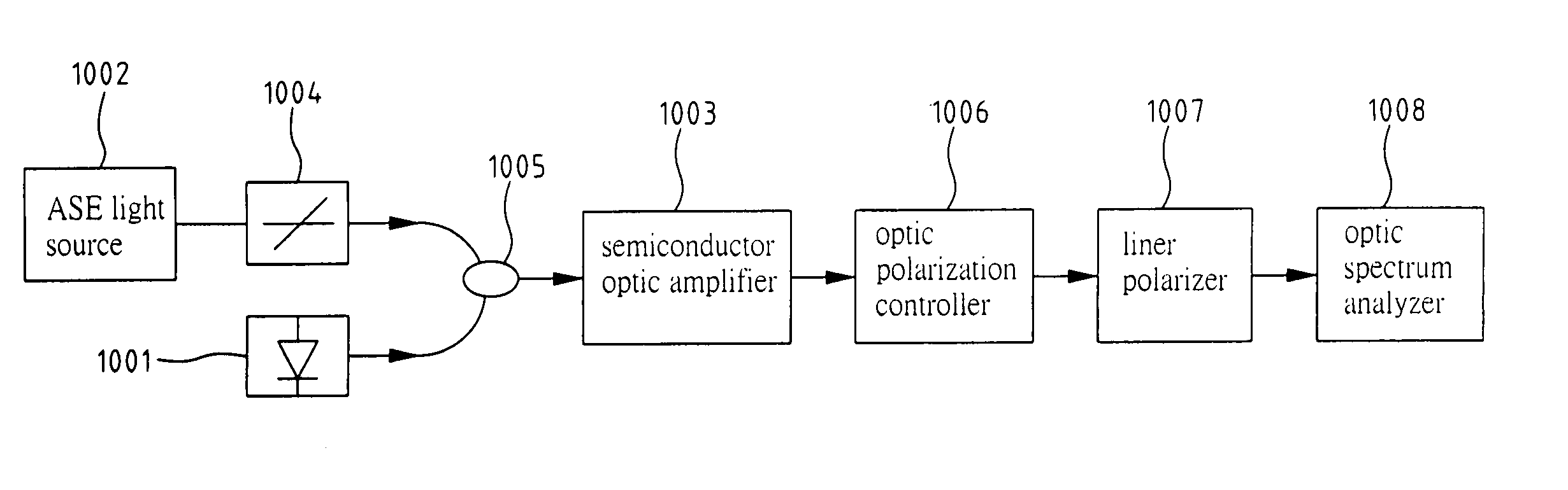
[0034] As fore mentioned, the present invention provides a non-sampling-based Q-factor measuring apparatus and method, which utilizes an optic power conversion module to convert the power variation of input optical signals in time domain into the variation in a non-time domain and replaces the conventional signal sampling mechanism for the same Q-factor measurement.

[0035] According to the present invention, the output of the optic power conversion connects to a non-time variant analytical mechanism. Via the non-time variant analytical mechanism, the statistical mean and standard deviation of the corresponding power variation in the non-time variant domain for the input optical signals at levels of 1 / 0 is obtained, and the Q-factor for the input optical signals is also easily measured.

[0036] With the present invention, the optic power variation in time domain can be transformed into non-time variant quantities, such as optical wavelength, optical polarization, and different output ...


PUM


Abstract

A non-sampling-based Q-factor measuring apparatus and method use a power conversion module to transform the power variation of inputted optical signals in time domain into the variation in other domains, such as optical wavelength, optical polarization and different output ports of optical elements. Taking optical wavelength as an example, different levels of power variation respond different outputs of wavelength variation through the use of a power-to-wavelength conversion module. An optical filter then separates the inputted optical signals with different wavelengths. The power average of a wavelength for its corresponding optical signals is further calculated by a photo detector. Thereby, the information of the power variation for the inputted optical signals at levels 1 and 0 can be obtained, and the Q-factor for the inputted optical signals is easily measured.

Description

FIELD OF THE INVENTION [0001] The present invention generally relates to a technique for optical signal measuring, and more specifically to an apparatus and method of non-sampling-based Q-factor measuring. BACKGROUND OF THE INVENTION [0002] The out blooming of information explosion as well as the rapid expanding of the worldwide networking applications naturally trigger the growing demand for channel bandwidth for data and signal transformation. The 10 Gbps Ethernet Standard for optical networking was announced in 2002. The major key to the current technology development and compatibility effort focuses on methods for fast and efficient information retrieval and transformation. The highly advanced information technology development countries in Europe, the United States, and Japan, all gear on aggressive research and development effort to achieve mass data information transformation via high speed optical networking as the foundation for information high way development. [0003] Unde...

Claims


Application Information

Patent Timeline
IPC IPC(8): G01N21/00
CPCH04L1/20
Inventor LEE, SAN-LIANGYANG, CHUN-LIANGHSU, DAR-ZU
Owner IND TECH RES INST
Why Eureka
Try Eureka