Needle Bearing and Speed Reducer Using The Needle Bearing

Active Publication Date: 2007-05-17
TEIJIN SEIKI CO LTD
View PDF5 Cites 7 Cited by
  • Summary
  • Abstract
  • Description
  • Claims
  • Application Information

AI Technical Summary

Benefits of technology

[0006] It is an object of this invention to provide a needle bearing in which any suitable material can be freely selected for a retainer, and a wall thickness of the retainer can be made small. Another object is to provide a speed reducer using such needle bearing.
[0008] In this invention, the radial inner end of the retainer is spaced radially outwardly from the radial outer end of the sliding-contact region where the needle rollers can be held in sliding contact with the restriction member. With this construction, the axial movement of each needle roller is limited not by the retainer but by the restriction member, and therefore a large axial force, developing as a result of skewing of the needle roller relative to its normal rotation axis, is received by the restriction member, and as a result the retainer, having low rigidity, can be satisfactorily used.
[0009] Therefore, any suitable material can be freely selected for the retainer, and for example a synthetic resin of a low strength can be selected, and besides the wall thickness of the retainer can be made small, and therefore its production cost as well as its weight can be reduced. When the wall thickness of the retainer and particularly the wall thickness of each bridge portion, disposed between any two adjacent restriction holes, are reduced, the multiple of the needle rollers can be increased, and by doing so, the torque-transmitting ability can be enhanced.
[0010] When the needle bearing is constructed so that the retainer has an inner diameter which is uniform over an entire axial length thereof, any flange portion is not formed at each of the opposite axial ends of the retainer, and therefore the effective axial length of the needle rollers can be increased, so that the torque transmitting-ability can be enhanced. And besides, the retainer is simplified in structure, and can be produced at low costs.
[0012] In the speed reducer, when the shaft is rotating relative to the external gear, the conical bearing imparts an axial flow to a lubricant within the speed reducer because of the contact angle. A gap is formed between the radial inner end of the retainer and that end of the inner ring (of the conical bearing) disposed close to the needle rollers, and therefore at this time, the lubricant flows into the needle bearing through this gap without being interrupted by the retainer, and can effectively lubricate the needle bearing. And besides, the very hard needle rollers can be brought into sliding contact with the very hard inner ring, and therefore even when the torque to be transmitted is made large, wear of these parts is small, so that a long lifetime can be obtained, and also the axial length of the speed reducer can be reduced.

Problems solved by technology

In the above needle bearing, there are occasions when the needle roller is skewed relative to its normal rotation axis because of misalignment.
However, the retainer must have enough rigidity to withstand such an axial force, and therefore there were encountered problems that the material for forming the retainer was limited to steel and that a wall thickness of the retainer need to be larger than a predetermined value.

Method used


Image

  • Needle Bearing and Speed Reducer Using The Needle Bearing
  • Needle Bearing and Speed Reducer Using The Needle Bearing
  • Needle Bearing and Speed Reducer Using The Needle Bearing

Examples


Embodiment Construction

[0020] One preferred embodiment of the present invention will now be described with reference to the drawings.

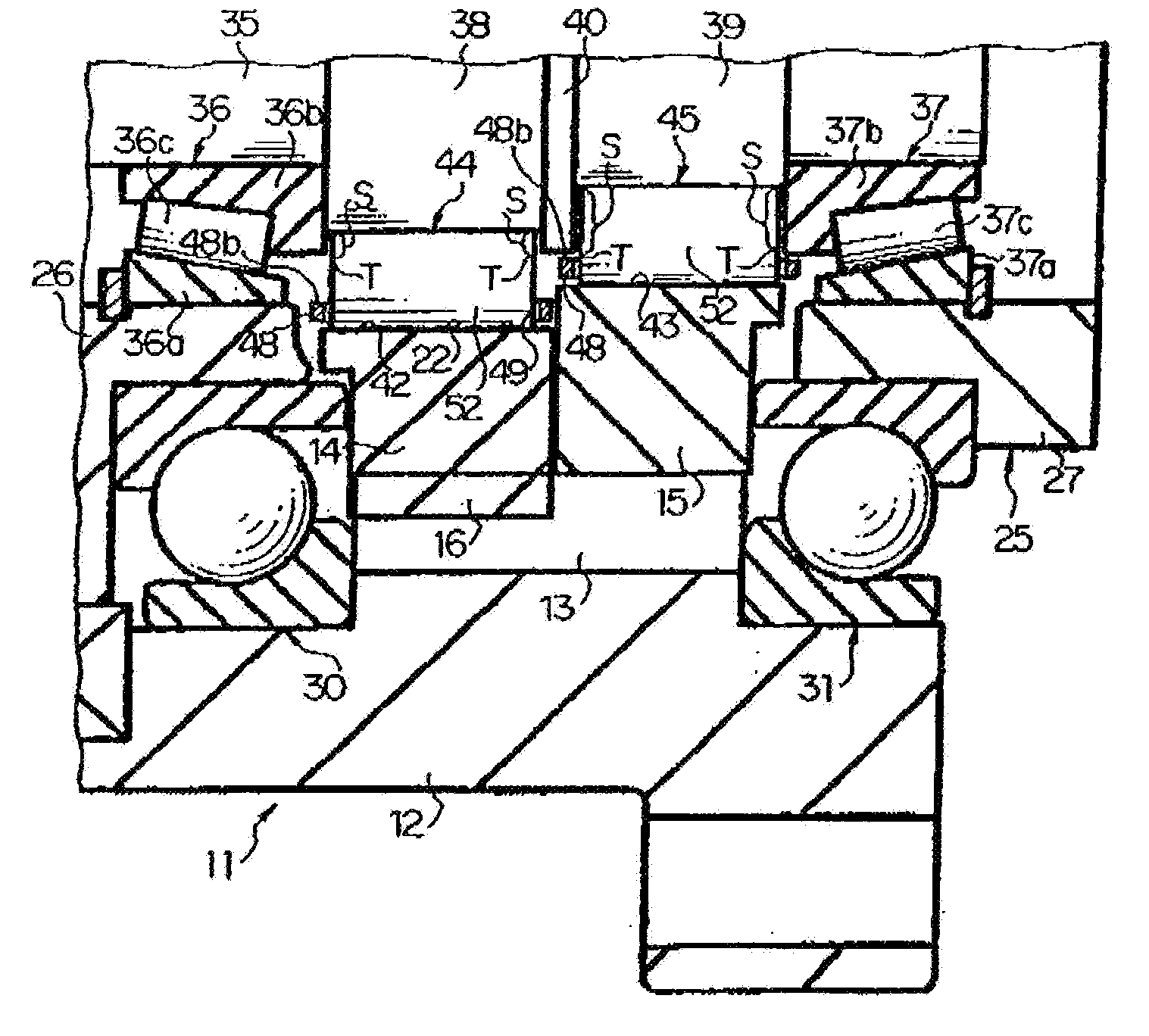
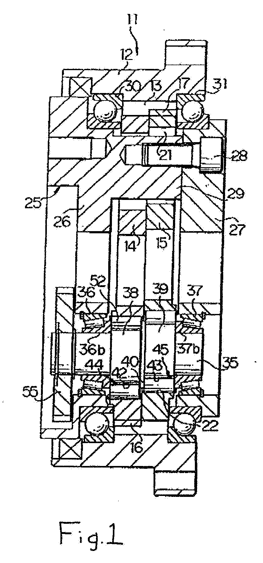
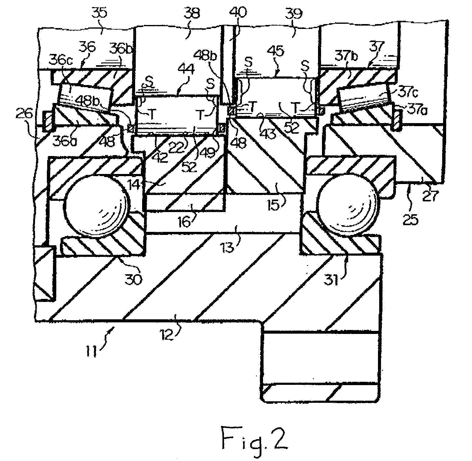
[0021] In FIGS. 1 and 2, reference numeral 11 denotes a planetary gear speed reducer (more specifically, an eccentric rotary-type speed reducer) used in a robot or the like, and this speed reducer 11 includes a rotary casing 12 (serving as an output member) mounted on an arm, a hand or the like (not shown). A multiple of internal-tooth pins 13 (serving as internal teeth) are fixed to an inner periphery of the rotary casing 12 in substantially half-inserted relation thereto, and these internal-tooth pins 13 extend in an axial direction, and are spaced at equal intervals in a circumferential direction. A plurality of (two) ring-like external gears 14 and 15 (serving as external members) are received within the rotary casing 12, and are juxtaposed to each other in the axial direction. External teeth 16 are formed on the outer periphery of the external gear 14, while external t...


PUM


Abstract

A radial inner end of a retainer is spaced radially outwardly from a radial outer end of a sliding-contact region, and with this construction the axial movement of each needle roller is limited not by the retainer but by an inner ring, and a restriction flange. Therefore, a large axial force developing in the needle rollers is received by the inner ring and the restriction flange, and as a result, the retainer having low rigidity can be satisfactorily used. Therefore, any suitable material such as a synthetic resin can be selected for the retainer, and besides the wall thickness of the retainer can be made small.

Description

CROSS-REFERENCE TO RELATED APPLICATIONS [0001] This application is a division of U.S. patent application Ser. No. 10 / 814,889 filed Mar. 31, 2004.BACKGROUND OF THE INVENTION [0002] This invention relates to a needle bearing and also to a speed reducer using this needle bearing. [0003] One known conventional needle bearing is disclosed, for example, in the above JP-UM-A-52-124353. This bearing comprises a retainer of an annular shape which includes a cylindrical tubular portion having a multiple of rectangular restriction holes (which are formed therein, extend in an axial direction, and are spaced at equal intervals in a circumferential direction), and also has flange portions projecting radially inwardly respectively from opposite axial ends of the cylindrical tubular portion, and a multiple of needle rollers which are received at their radially-outward end portions in the restriction holes, respectively, and are restricted in axial movement by the flange portions. A radial length o...

Claims


Application Information

Patent Timeline
IPC IPC(8): F16H35/00F16C35/063F16C19/36F16C19/44F16C19/46F16C33/46F16H1/32
CPCF16C19/46F16C33/4635Y10T74/19F16H1/32F16C2361/61F16C2240/84F16C19/44
Inventor TANAKA, MINORUKURITA, MASAKAZUNAKAMURA, KOJI
Owner TEIJIN SEIKI CO LTD
Why Eureka
Try Eureka