
Multiple Video Display Configurations & Bandwidth Conservation Scheme for Transmitting Video Over a Network

a video display and network technology, applied in the field of digital video transmission systems, can solve the problems of incompatible concept, inability to support continuous source playback, fundamentally incompatible time stamping mechanism used by media players, etc., to prevent network congestion and demand network bandwidth

Inactive Publication Date: 2007-05-10
PR NEWSWIRE
View PDF99 Cites 59 Cited by
  • Summary
  • Abstract
  • Description
  • Claims
  • Application Information

AI Technical Summary

Benefits of technology

[0021] Streaming video signals tend to be bandwidth-intensive. Furthermore, since each monitor is capable of displaying up to 16 separate video images, the bandwidth requirements of the system can potentially be enormous. It is thus desirable to minimize the bandwidth requirements of the system.
[0024] However, when the user subdivides a video display area into a 3×3 array, the demand on network bandwidth is 9 times higher than in the single-display example. And when the user subdivides the video display area into a 4×4 array, the network bandwidth requirement is 16 times that of a single display. To prevent network congestion, video images in a 3×3 or 4×4 array are obtained from the low-resolution, low-speed stream of the desired encoder. Ultimately, no image resolution is lost in these cases, since the actual displayed video size decreases as the screen if subdivided. That is, if a higher-resolution image were sent by the encoder, the image would be decimated anyway in order to fit it within the available screen area. It is, therefore, an object and feature of the subject invention to provide the means and method for displaying “live” streaming video over a commercially available media player system. It is a further object and feature of the subject invention to provide the means and method for permitting multiple users to access and view the live streaming video at different time, while in process without interrupting the transmission.

Problems solved by technology

However, difficulties arise from the fact that the MPEG-1 format was designed primarily to support playback of recorded video from a video CD, rather than to support streaming of ‘live’ sources such as surveillance cameras and the like.
Media Player, like MPEG-1 itself, is inherently file-oriented and does not support playback of continuous sources such as cameras via a network.
This is incompatible with the concept of a continuous streaming source, which may not have a filename and which has no definable file length.
Moreover, the time stamping mechanism used by Media Player is fundamentally incompatible with the time stamping scheme standardized by the MPEG-1 standard.

Method used


Image

  • Multiple Video Display Configurations & Bandwidth Conservation Scheme for Transmitting Video Over a Network
  • Multiple Video Display Configurations & Bandwidth Conservation Scheme for Transmitting Video Over a Network
  • Multiple Video Display Configurations & Bandwidth Conservation Scheme for Transmitting Video Over a Network

Examples


Embodiment Construction

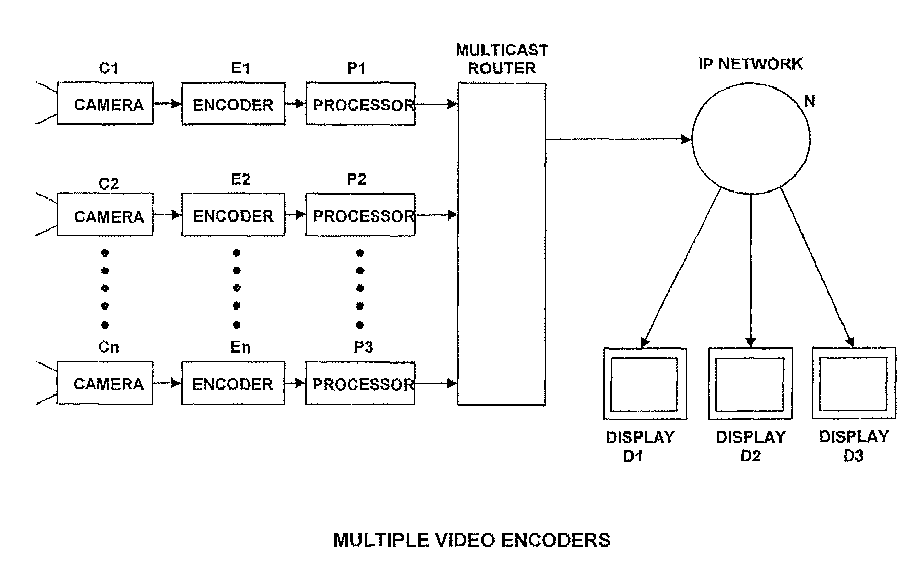
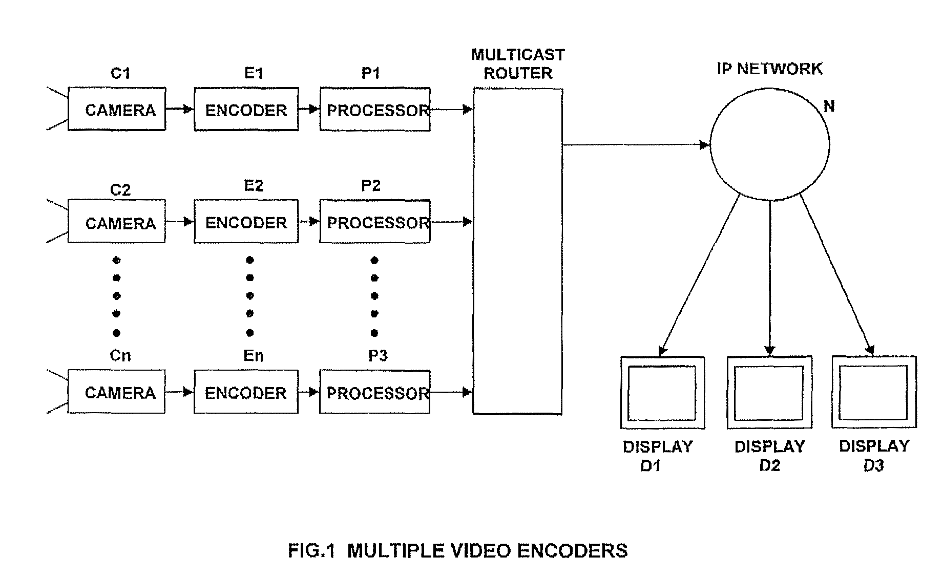
[0031] The video surveillance system of the subject invention is specifically adapted for distributing digitized camera video on a real-time or near real-time basis over a LAN and / or a WAN. As shown in FIG. 1, the system uses a plurality of video cameras C1, C2 . . . Cn, disposed around a facility to view scenes of interest. Each camera captures the desired scene, digitizes the resulting video signal at a dedicated encoder module E1, E2 . . . En, respectively, compresses the digitized video signal at the respective compressor P1, P2 . . . Pn, and sends the resulting compressed digital video stream to a multicast address router R. One or more display stations D1, D2 . . . Dn may thereupon view the captured video via the intervening network N. The network may be hardwired or wireless, or a combination, and may either a Local Area Network (LAN) or a Wide Area Network (WAN), or both.

[0032] The preferred digital encoders E1, E2 . . . En produce industry-standard MPEG-1 digital video str...


PUM


Abstract

A system for capturing, encoding and transmitting continuous video from a camera to a display monitor via a network includes a user friendly interface wherein a map is provided at a display screen for illustrating the location of the cameras and indicating the direction of the camera angle. The monitor includes a display area for selectively displaying selected cameras and for controlling the selection, display and direction of the cameras from a remote location. The display screen can be configured to display one or any combination of cameras. The cameras can be selected by manual selection, pre-programmed sequencing or by event detection with the selected camera automatically displayed on the display area. Secondary monitors may be incorporated to enhance the display features. The secondary monitors are controlled by the control panel provided on the primary monitor.

Description

BACKGROUND OF INVENTION [0001] 1. Field of Invention [0002] The invention is generally related to digital video transmission systems and is specifically directed to a method and apparatus for compressing and distributing digitized video over a network for supporting the transmission of live, near real-time video data in a manner to maximize display options while conserving bandwidth requirements. [0003] 2. Description of the Prior Art [0004] Cameras employ digital encoders that produce industry-standard digital video streams such as, by way of example, MPEG-1 streams. The use of MPEG-1 streams is advantageous due to the low cost of the encoder hardware, and to the ubiquity of software MPEG-1 players. However, difficulties arise from the fact that the MPEG-1 format was designed primarily to support playback of recorded video from a video CD, rather than to support streaming of ‘live’ sources such as surveillance cameras and the like. [0005] MPEG system streams contain multiplexed ele...

Claims


Application Information

Patent Timeline
Patent Type & Authority Applications(United States)
IPC IPC(8): H04N7/173
CPCH04N7/181H04N21/21805H04N21/2365H04N21/4316H04N21/4347H04N21/44222H04N19/179H04N21/6405H04N19/102H04N19/61H04N19/12H04N19/136H04N19/162H04N21/4858H04N21/44224
Inventor MONROE, DAVID A.BAIRD, JOHN M.
Owner PR NEWSWIRE
Learn More