Programmable attenuator using digitally controlled CMOS switches

a technology of cmos switch and attenuator, which is applied in the direction of amplification control details, electrical apparatus, radio transmission, etc., can solve the problem of challenging the implementation of direct-conversion tuners for satellite broadcasting

Active Publication Date: 2007-05-10
AVAGO TECH INT SALES PTE LTD
View PDF2 Cites 40 Cited by
  • Summary
  • Abstract
  • Description
  • Claims
  • Application Information

AI Technical Summary

Problems solved by technology

Implementing a direct-conversion tuner for satellite broadcasting is challenging due to wide input signal bandwidths (e.g., ranging from 950˜2150 MHz) and low received power levels (e.g., ranging from −25˜−70 dBm).
In addition, due to the many broadcasting channels and satellites, Digital Broadcasting System (DBS) receivers must contend with large numbers of unwanted channel interferers.

Method used


Image

  • Programmable attenuator using digitally controlled CMOS switches
  • Programmable attenuator using digitally controlled CMOS switches
  • Programmable attenuator using digitally controlled CMOS switches

Examples


Embodiment Construction

[0016] The following detailed description of the present invention refers to the accompanying drawings that illustrate exemplary embodiments consistent with this invention. Other embodiments are possible, and modifications may be made to the embodiments within the spirit and scope of the invention. Therefore, the detailed description is not meant to limit the invention. Rather, the appended claims define the scope of the invention.

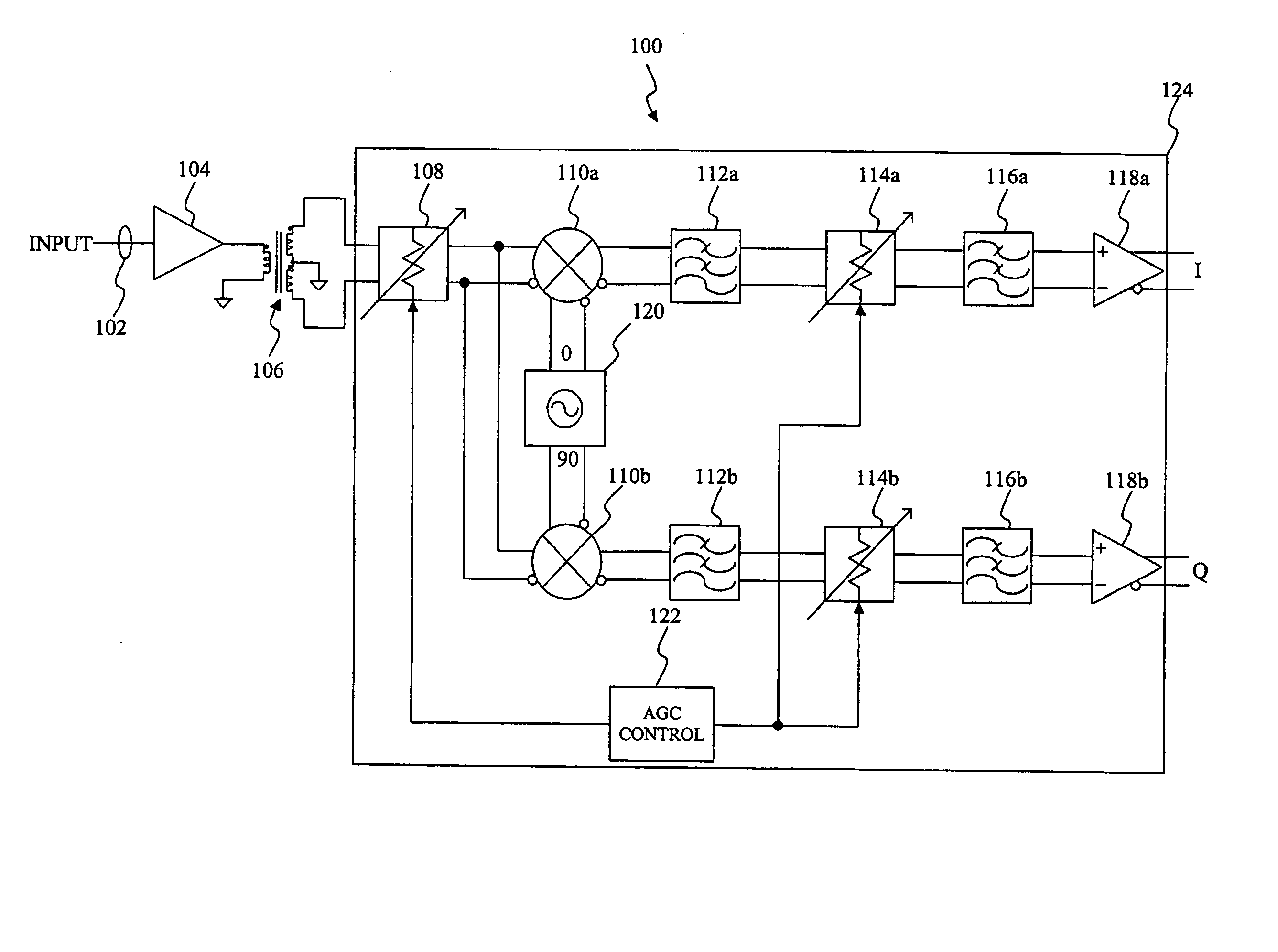
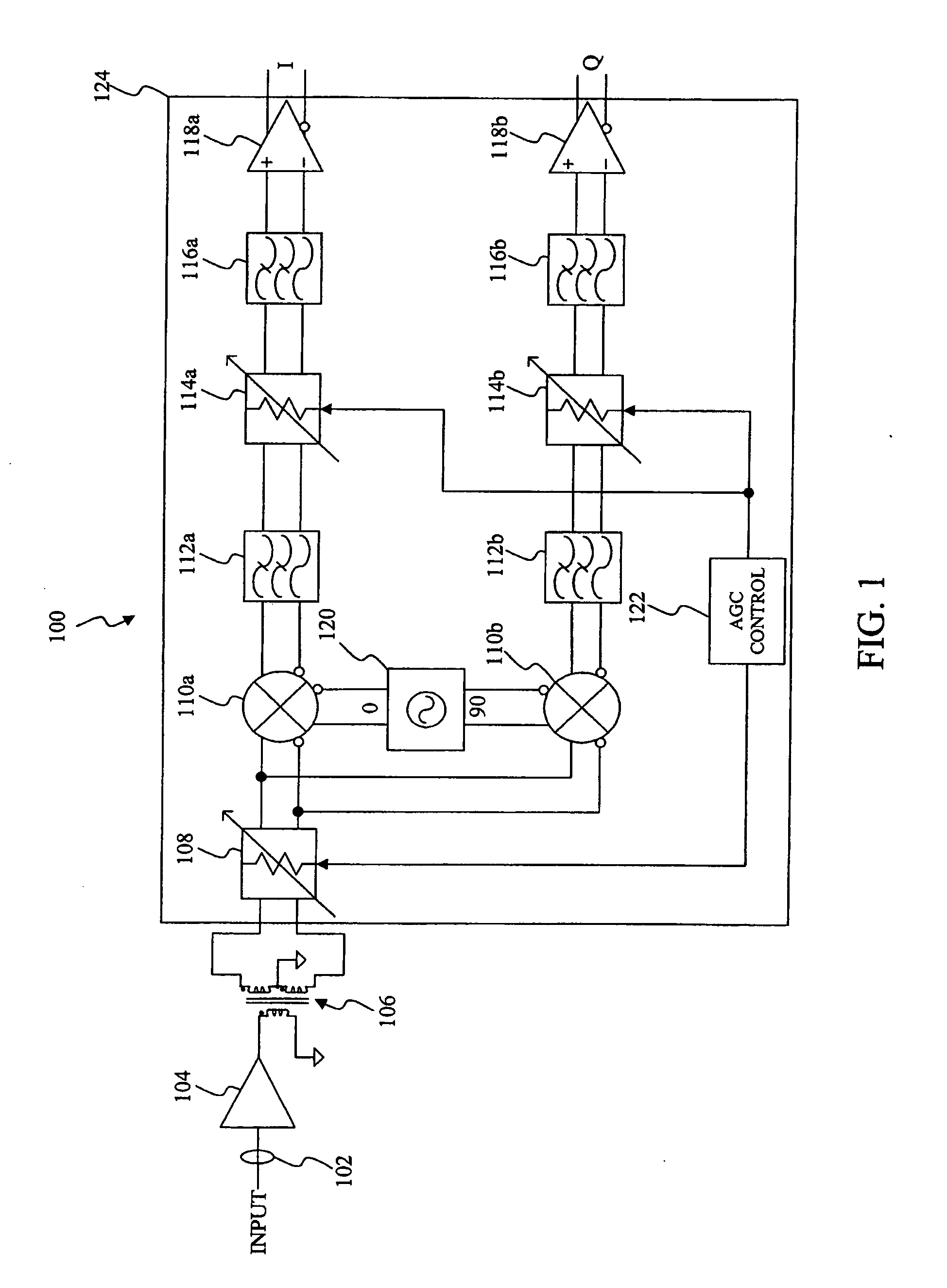
[0017]FIG. 1 illustrates a direct-conversion receiver having a programmable attenuator according to an exemplary embodiment of the present invention. Direct conversion receiver 100 may receive an input, denoted as input 102, from an antenna or any other suitable source. Direct conversion receiver 100 down-converts input 102 directly to baseband in a single downconversion. By directly translating input 102 to baseband, direct conversion receiver 100 eliminates intermediate frequency (IF) stages and the image-rejection requirement of front end filters. As a...


PUM


Abstract

A programmable attenuator includes a resistor ladder having a plurality of taps to provide a coarse gain control. Coupled to each tap is a plurality of switches. Control logic activates or deactivates individual switches in the plurality of switches to provide a fine gain control. More specifically, a set of activated switches provides fine gain control by determining an overall attenuation level interpolated between an adjacent pair of taps.

Description

CROSS-REFERENCE TO RELATED APPLICATIONS [0001] This application claims the benefit of U.S. Provisional Patent Application No. 60 / 733,253, filed Nov. 4, 2005, entitled “A Programmable Attenuator Using Digitally Controlled Switches,” which is incorporated by reference herein in its entirety.BACKGROUND OF THE INVENTION [0002] 1. Field of the Invention [0003] The present invention is related to a programmable attenuator. [0004] 2. Background Art [0005] Communication systems allow for communication over large distances by using sophisticated transponders in a satellite. Transponders receive incoming communications over a band of frequencies, the uplink, and retransmit the communications over another band of frequencies, the downlink, at the same time. [0006] The uplink originates from a point on surface of the Earth, usually a ground station, to the transponder. A receiver in the transponder receives the incoming communication during the uplink. The transponder sends the downlink to a po...

Claims


Application Information

Patent Timeline
Patent Type & Authority Applications(United States)
IPC IPC(8): H04B7/185H04B1/06
CPCH03G1/0088H03G3/001
Inventor CHANG, SUNG-HSIENGOMEZ, RAMON
Owner AVAGO TECH INT SALES PTE LTD
Why Eureka
Try Eureka