
Seal device with sensor and rolling bearing device using the same

a technology of sealing device and rolling bearing, which is applied in the direction of mechanical equipment, instruments, transportation and packaging, etc., can solve the problems of water entering the fitting portion, the rolling bearing device is difficult to apply to the hub unit of the vehicle, and the gap can occur between resin, so as to reduce the axial dimension of the rolling bearing device and facilitate the installation. , the effect of enhancing the rigidity

Inactive Publication Date: 2007-05-10
JTEKT CORP +1
View PDF7 Cites 5 Cited by
  • Summary
  • Abstract
  • Description
  • Claims
  • Application Information

AI Technical Summary

Benefits of technology

[0011] An object of the present invention is to provide a seal device with a sensor and a rolling bearing device using the seal device. In the seal device and the rolling bearing device, the axial dimensions thereof can be reduced, and the separation between core metal and resin member and the intrusion of water from the boundary between the core metal and the resin member can be prevented. Further, the rigidity of the fitting portion between a rotated seal member and a rotating member can be enhanced.
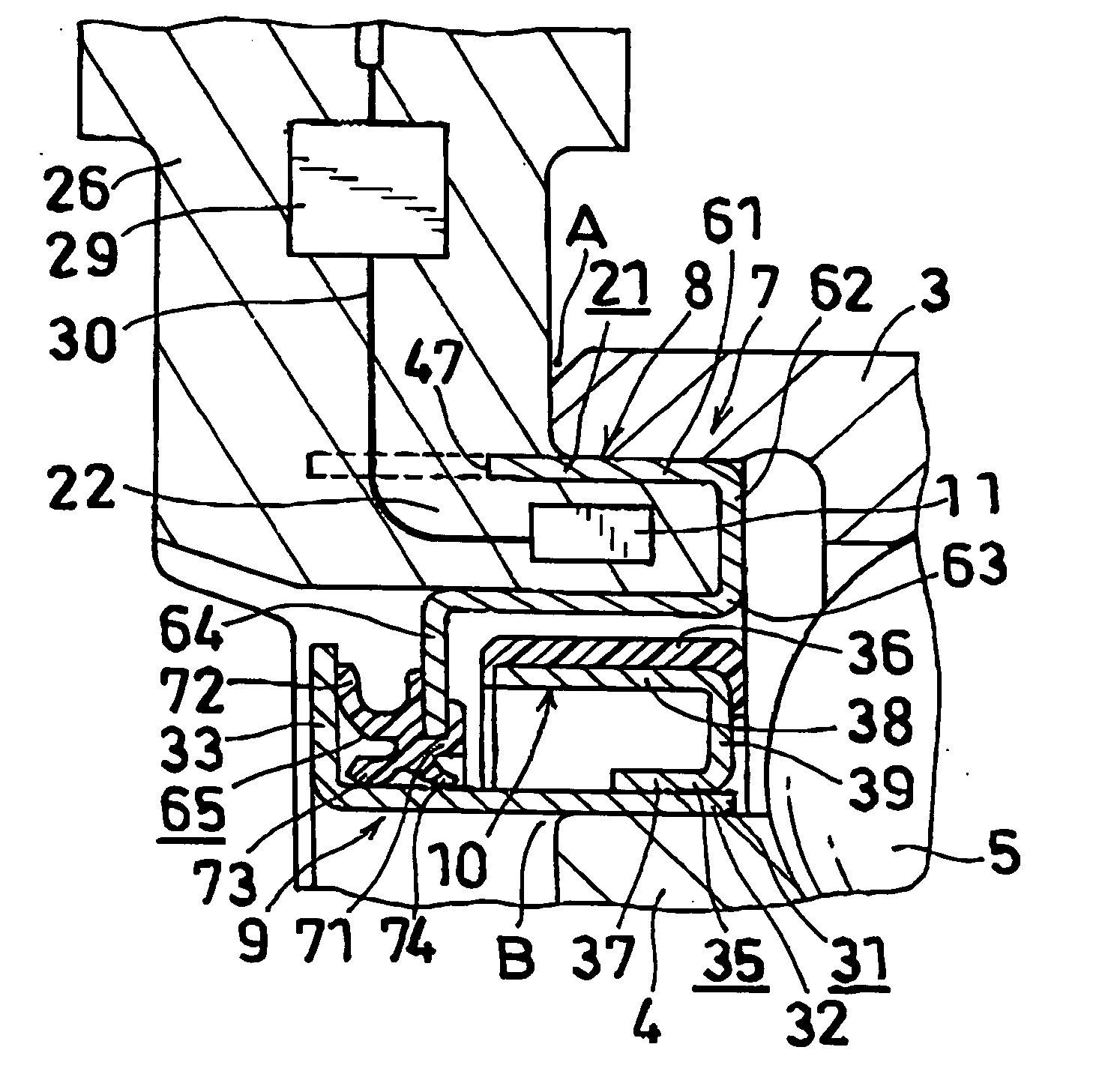
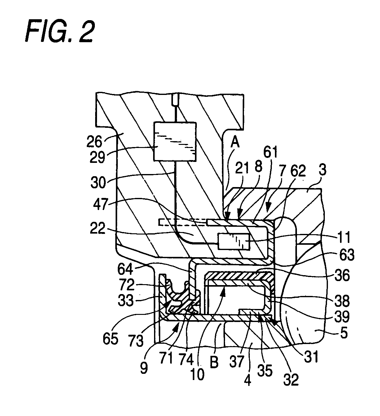
[0015] a core metal including a cylindrical fitting portion which is insert-molded to the fixed member so that an axial outer end portion of the cylindrical fitting portion is positioned within resin, a first flange portion that continues to an axial inner end portion of the cylindrical fitting portion, and a first cylindrical portion for preventing water from invading which continues to the first flange portion so as to extend outward in an axial direction;
[0024] The elastic seal is provided in the flange portion of the rotated seal member so as to come in sliding contact with the cylindrical portion for preventing water from invading. Alternately, the elastic seal is provided in the flange portion provided in the axial outer end portion of the cylindrical portion for preventing water from invading so as to come in sliding contact with the cylindrical portion of the rotated seal member and / or the flange portion.
[0029] The small-diameter cylindrical portion of the support member of the pulsar is fitted and fixed to the axial inner portion of the cylindrical portion of the rotated seal member such that the connecting portion is set inward in the axial direction. Then, the fitting portion between the cylindrical portion of the rotated seal member and the rotating member is reinforced by the small-diameter cylindrical member of the support member of the pulsar, which makes it possible to enhance the rigidity thereof.
[0030] Preferably, the small-diameter cylindrical portion of the support member of the pulsar has a smaller axial length than the large-diameter cylindrical portion. The large-diameter cylindrical portion needs to have a certain axial length such that the magnetized body is provided therein. Further, in terms of rigidity, it is preferable that the small-diameter cylindrical portion is set to have the same axial length as the large-diameter cylindrical portion. In this case, however, it is difficult to perform press molding. When the small-diameter cylindrical portion of the support member of the pulsar is fitted and fixed to the rotated seal member such that the connecting portion is set inward in the axial direction, the rigidity can be sufficiently enhanced even though the axial length of the small-diameter cylindrical portion is set to be smaller than the large-diameter cylindrical portion. As such, it is possible to enhance the rigidity without degrading the productivity.
[0034] The seal device with a sensor according to the present invention includes the fixed seal member and the rotated seal member, and the fixed seal member has a sensor resin-molded to the core metal. Therefore, the sensor is mounted into the seal device. For example, when the sensor is attached to the rolling bearing, the sensor is easily embedded in the rolling bearing. Further, it is possible to reduce the axial dimension of the rolling bearing device with a sensor. Furthermore, since the outer end portion of the cylindrical fitting portion is insert-molded so as to be positioned within the resin, the core metal is not removed from the resin by a torque at the time of rotation. In addition, the elastic seal is provided in at least one of the axial outer end portion of the cylindrical portion for preventing water from invading and the axial outer end portion of the rotated seal member, the elastic seal coming in sliding contact with the other. Therefore, although water invades from the gap occurring between the core metal and the resin after the cylindrical fitting portion of the core metal is fitted and fixed to the fixed member, the water is delivered outward in the axial direction from the space between the resin and the cylindrical portion for preventing water from invading through between the cylindrical fitting portion and the resin and between (the outer surface in an axial direction of) the flange portion and the resin. Therefore, the water is prevented from invading into a device having the seal device with a sensor attached thereto. Further, the fitting portion between the cylindrical portion of the rotated seal member and the rotating member is reinforced by the small-diameter cylindrical portion of the support member of the pulsar, which makes it possible to enhance the rigidity thereof. Therefore, it is possible to further enhance a seal property.

Problems solved by technology

In the rolling bearing device of Patent Document 1, the ring-shaped magnet and the sensor supporting member are formed so as to project more than the bearing device in the axial direction, which makes it difficult to apply the rolling bearing device to a hub unit of a vehicle.
In this case, however, a gap can occur between resin and the core metal holding the resin as the resin contracts, the core metal and the resin can be separated from each other, or water can invade into the bearing from the boundary between the core metal and the resin.
When the rigidity of the fitting portion is low, it is highly likely that water invades from the fitting portion.

Method used


Image

  • Seal device with sensor and rolling bearing device using the same
  • Seal device with sensor and rolling bearing device using the same
  • Seal device with sensor and rolling bearing device using the same

Examples


Embodiment Construction

[0038] Hereinafter, a preferred embodiment of the present invention will be described with reference to accompanying drawings.

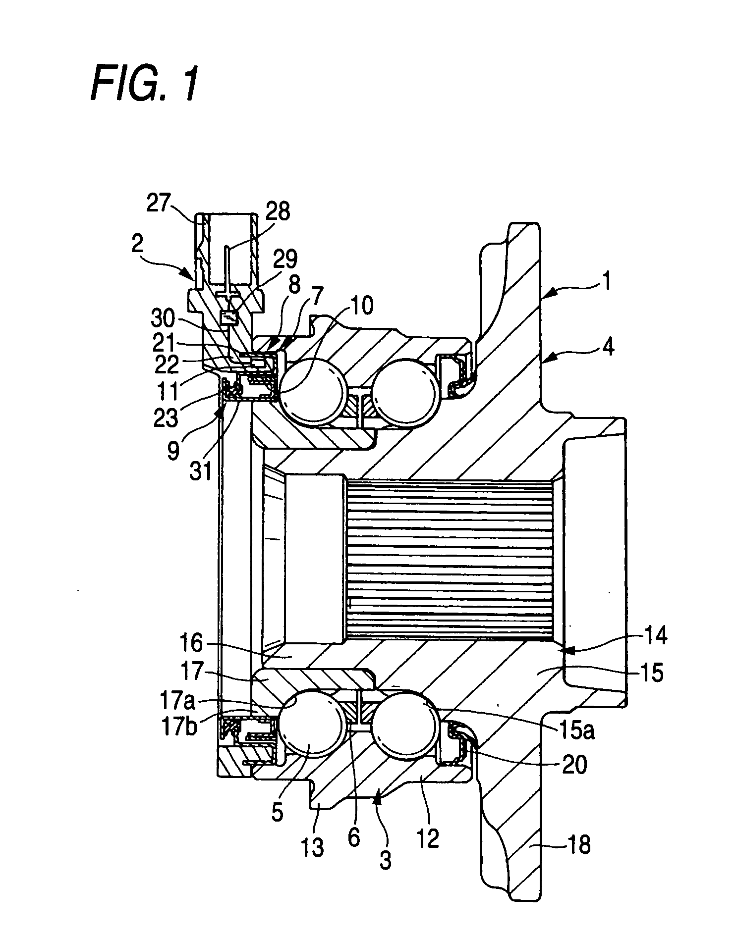
[0039]FIGS. 1 and 2 are diagrams illustrating a seal device with a sensor and a rolling bearing device using the seal device according to an embodiment of the invention. In the following descriptions, the left and right sides are referred to as the left and right sides of FIG. 1, respectively. Further, the left side becomes the inside of a rolling stock, and the right side becomes the outside of the rolling stock.

[0040] The rolling bearing device includes a hub unit 1, a sensor device 2 provided in the hub unit 1, and a pulsar 10 which is a portion to be detected.

[0041] The hub unit 1 includes a body-side raceway member 3 fixed to a body side, a wheel-side raceway member 4 on which a wheel is attached, a plurality of balls 5 serving as rolling elements which are arranged in two lines between both of the members 3 and 4, and a holder 6 which holds the respe...


PUM


Abstract

A seal device with a sensor includes a fixed seal member fixed to a body-side raceway member and a rotated seal member fixed to a body-side raceway member. The rotated seal member comprises a pulsar provided with a support member and a magnetized body. The support member of the pulsar includes a small-diameter cylindrical portion fitted and fixed to a cylindrical portion of the rotated seal member, a large-diameter cylindrical portion having the magnetized body provided therein, and a connecting portion connecting both of the cylindrical portions. The support member of the pulsar is fitted and fixed to the axial inner portion of the cylindrical portion of the rotated seal member such that the connecting portion is set inward in the axial direction.

Description

BACKGROUND OF THE INVENTION [0001] The present invention relates to a seal device mounting a sensor device and a rolling bearing device using the seal device. [0002] Since vehicles need various kinds of information for performing control, it has been proposed that a hub unit (a rolling bearing device) has a sensor device provided therein. The hub unit includes a wheel-side raceway member to which a wheel is attached, a body-side raceway member which is fixed to a body side, and two lines of rolling elements arranged between both of the wheel-side raceway member and the body-side raceway member. [0003] As such a rolling bearing device, Patent Document 1 discloses a rolling bearing device including an outer ring, an inner ring, rolling elements arranged between both of the outer and inner rings, and seal disposed between the end portions of both of the outer and inner rings. On the end surface of the outer ring, a sensor supporting member having a sensor provided thereon is attached. ...

Claims


Application Information

Patent Timeline
Patent Type & Authority Applications(United States)
IPC IPC(8): F16C41/04F16C41/00B60B35/18F16C19/18F16C19/52F16C33/78F16J15/326F16J15/328G01P3/487
CPCF16C2326/02F16J15/326G01P3/443F16C41/007F16C33/78
Inventor KOYAGI, KATSURAKUWAJIMA, TOORUKAGEYAMA, TAKESHI
Owner JTEKT CORP
Learn More