
Method to control thickness in composite parts cured on closed angle tool

a closed angle tool and composite material technology, applied in the field of composite material preparation, can solve the problems of excessive thickness in the radius beyond, inner radius, tie, and hindered, and achieve the effect of greater uniformity

Active Publication Date: 2007-05-10
THE BOEING CO
View PDF7 Cites 28 Cited by
  • Summary
  • Abstract
  • Description
  • Claims
  • Application Information

AI Technical Summary

Benefits of technology

The present invention provides a method for controlling the thickness of composite laminates cured on closed angel tools. This method uses a peel ply instead of a breather, which allows for the formation of composite parts with greater uniformity and without the need for extra hardware. The resulting composite parts can be used in a wide variety of applications, such as automotive and aerospace. The invention is particularly useful for forming shear ties in commercial aircraft, which are used to secure the inner framework of the aircraft to the airplane skin.

Problems solved by technology

Excessive thickening in the radius beyond the allowable thickness tolerance produces two main problems.
Second, fasteners, which need to be located near the inner radius of the shear tie, will be hindered if the thickness of the radius region encroaches on the web or the flange.
Either scenario may result in the compromise of mechanical properties or assembly fit-up.
While RPI can achieve parts having substantially uniform thicknesses, there are disadvantages in utilizing the RPI process.
Further, if the laminate part is cycled multiple times utilizing the RPI method, the thickness of the inner radii may be thinned, thus affecting the uniformity of thickness of the part.
However, the use of cauls may cause bulges or thinner areas outside the allowable tolerances in the web and flange.
Even if this problem is overcome the fabrication, handling, maintenance, and periodic replacement of the many different cauls would be cost prohibitive.

Method used


Image

  • Method to control thickness in composite parts cured on closed angle tool
  • Method to control thickness in composite parts cured on closed angle tool
  • Method to control thickness in composite parts cured on closed angle tool

Examples


Embodiment Construction

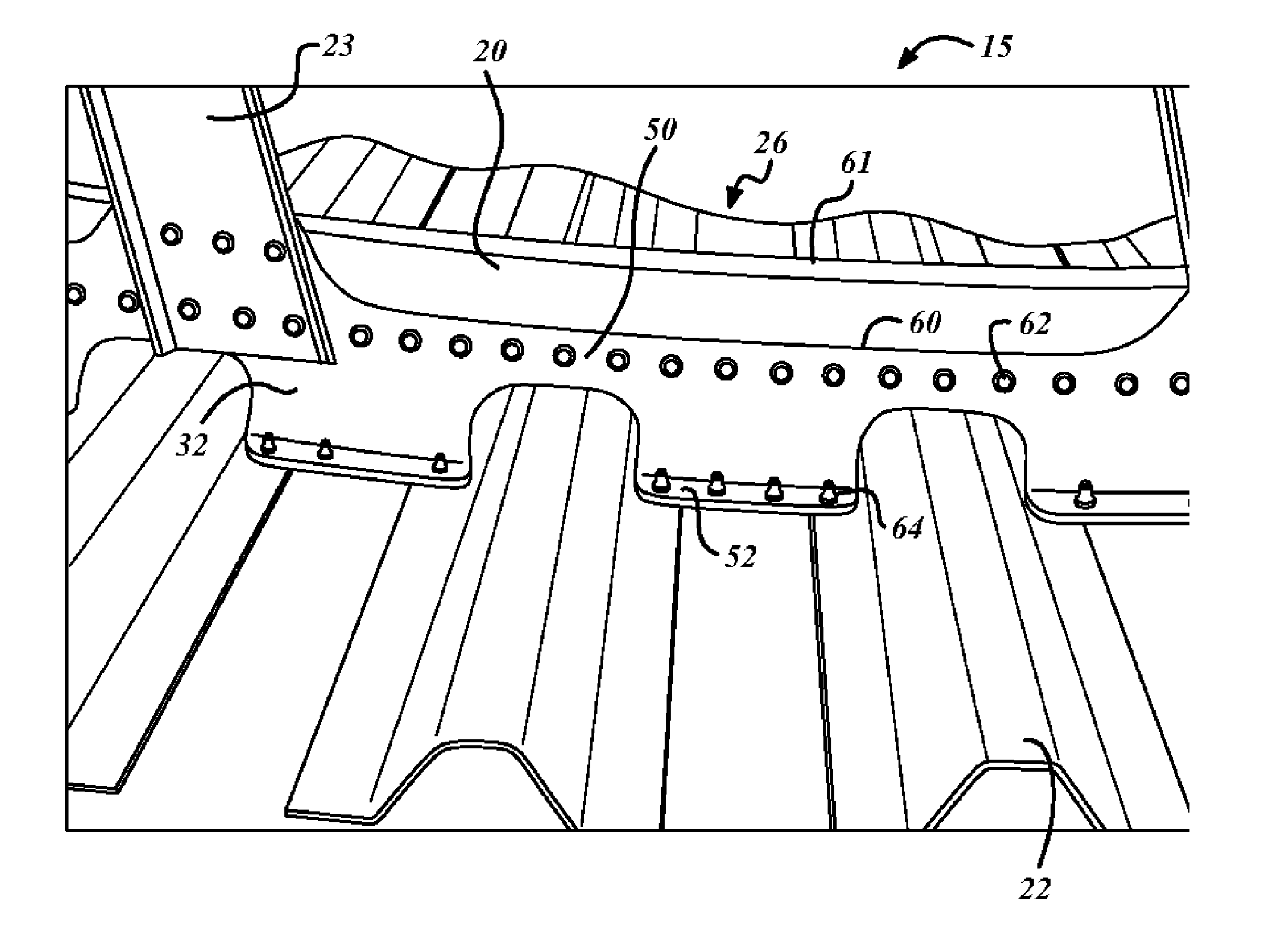
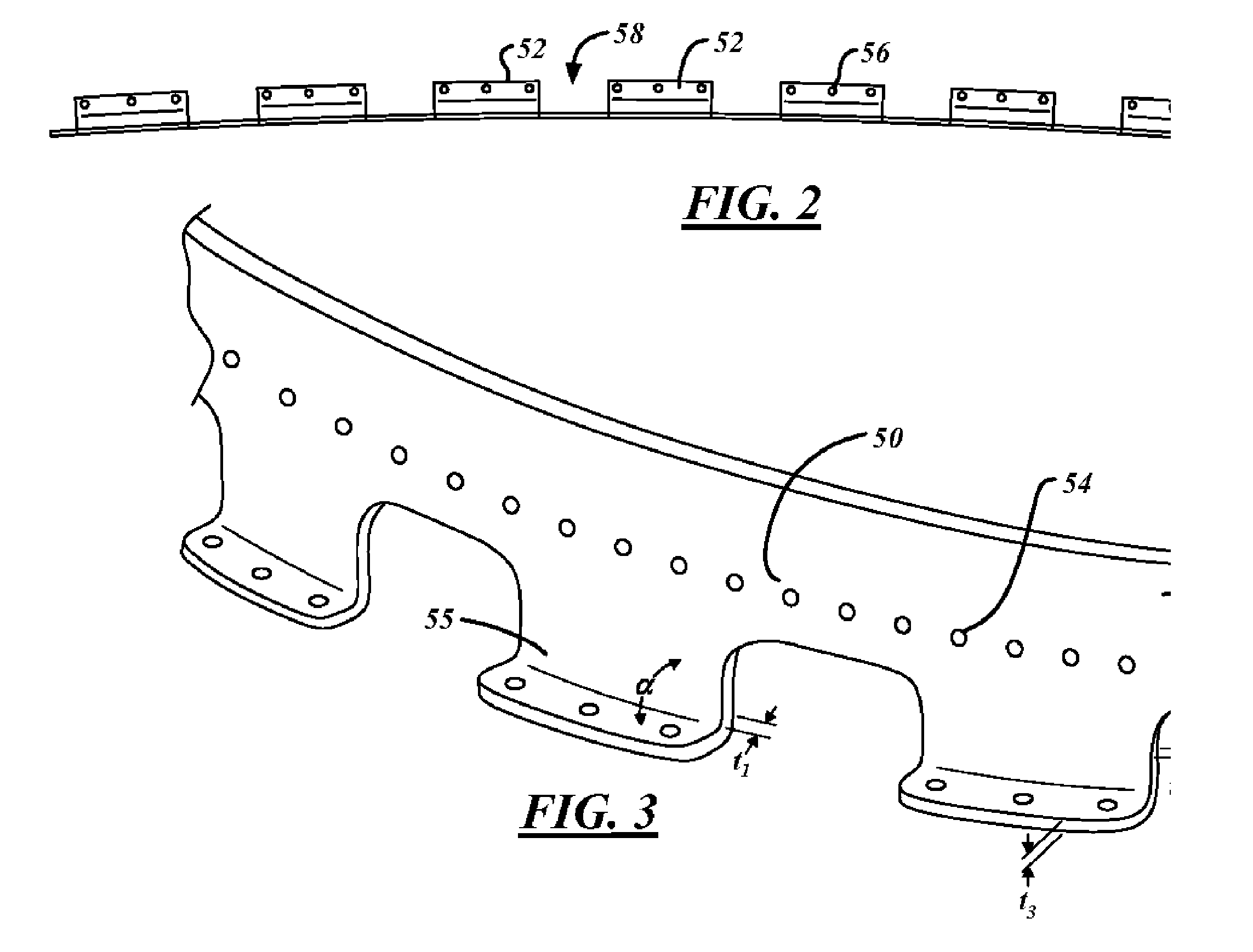
[0014] The present invention provides a method of forming a composite prepreg material into a closed angle shape and processing the material in a manner that results in a cured component that is consistent throughout its thickness. The present invention finds applicable uses in a wide variety of potential applications, including for example, in the aerospace and automotive industry. The preferred method of the present invention is ideally suited for forming a composite shear tie 32 that is utilized in the supporting framework of a commercial aircraft. A method for forming a shear tie, as one illustrative non-limiting example of a potential end use, will be described further herein below in FIGS. 1-3 and 5-11.

[0015] Referring to FIGS. 1 and 2, a perspective and partial view of an aircraft fuselage 15, the construction thereof may be observed to consist of a support frame structure 26 that includes a series of spaced circumferential frame members 20 that define the overall cross sect...


PUM

PropertyMeasurementUnit
angleaaaaaaaaaa
angleaaaaaaaaaa
angleaaaaaaaaaa

Abstract

The present invention provides a method for controlling the thickness of composite laminates cured on closed angel tools. The invention utilizes a peel ply rather than a breather during the preparation for cure of laminate parts having a substantially uniform initial thickness. This method allows composite parts to be formed with greater uniformity and without the need for extra hardware. The composite part formed by the above method may find use in a wide variety of applications, including, for example, automotive and aerospace applications. Thus, for example, a composite part formed in accordance with the present invention is ideally suited for use as a shear tie in a commercial aircraft, which are used to secure the inner framework of the aircraft to the airplane skin.

Description

TECHNICAL FIELD [0001] The present invention generally relates to preparation of shaped composite materials and more specifically to a method for controlling the thickness of composite parts formed on a closed angle tool. BACKGROUND ART [0002] Cured laminate composite parts may conventionally be formed from preimpregnated (“prepreg”) tape of epoxy and carbon or glass fiber. The prepreg plies are shaped (i.e. bent or curved) and applied to a female curing tool. Conventional processing on female cure tools produces out of tolerance laminate thickness conditions with radii that are thicker than nominal regions. Excessive thickening in the radius beyond the allowable thickness tolerance produces two main problems. First, there will either be large resin pockets between a few plies or the resin layers between many plies will be thicker than normal. Second, fasteners, which need to be located near the inner radius of the shear tie, will be hindered if the thickness of the radius region en...

Claims


Application Information

Patent Timeline
Patent Type & Authority Applications(United States)
IPC IPC(8): B29C47/76B29C48/76
CPCB29C70/342B29C70/44
Inventor MCGOWAN, EVA V.ZENKNER, GRANT C.
Owner THE BOEING CO
Learn More