
Modular fixed and mobile bearing prosthesis system

a technology of fixed bearings and bearings, applied in the field of human knee prosthesis, can solve the problems of affecting the stability of the knee joint, the failure of the primary prosthesis, and the inability to meet the femoral component and the bearing componen

Active Publication Date: 2007-05-03
DEPUY (IRELAND) LTD
View PDF65 Cites 85 Cited by
  • Summary
  • Abstract
  • Description
  • Claims
  • Application Information

AI Technical Summary

Benefits of technology

The present invention provides a prosthetic knee system with a femoral component, a tibial base component, and two tibial bearing components. The femoral component has bearing surfaces, the tibial base component has a tray and a stem, and the stem extends from the tray. The stem has a longitudinal axis and a distal end. The two tibial bearing components have a proximal bearing surface, a flat distal surface, and a stem extending distally from the distal surface. The stem has a longitudinal axis and a distal end. The longitudinal bore in the stem is non-circular in cross-section. The stem has a maximum transverse dimension at a protrusion and a minimum transverse dimension at the distal end of the stem. The invention also provides a method for assembling the components with the stem of the tibial base component received in the longitudinal bore of the tray. The technical effects of the invention include improved stability, reduced wear, and improved rotational positioning of the bearing components.

Problems solved by technology

In typical fixed bearing designs where the bearing and the base are locked around their peripheries, the size of the bearing component is dictated by the size and features of the tibial base component, so that the bearing component is properly fixed in position on the base; accordingly, the match between the femoral component and the bearing component may not be ideal.
However, if the soft tissue of the knee joint is in poor condition (e.g. the collateral ligaments are compromised), it may be advisable to use a fixed bearing design to provide the patient with greater stability.
On occasion, the primary prosthesis fails.
Failure can result from many causes, including wear, aseptic loosening, osteolysis, ligamentous instability, arthrofibrosis and patellofemoral complications.
This change can result from several factors, such as deterioration of the knee ligaments.

Method used


Image

  • Modular fixed and mobile bearing prosthesis system
  • Modular fixed and mobile bearing prosthesis system
  • Modular fixed and mobile bearing prosthesis system

Examples


Embodiment Construction

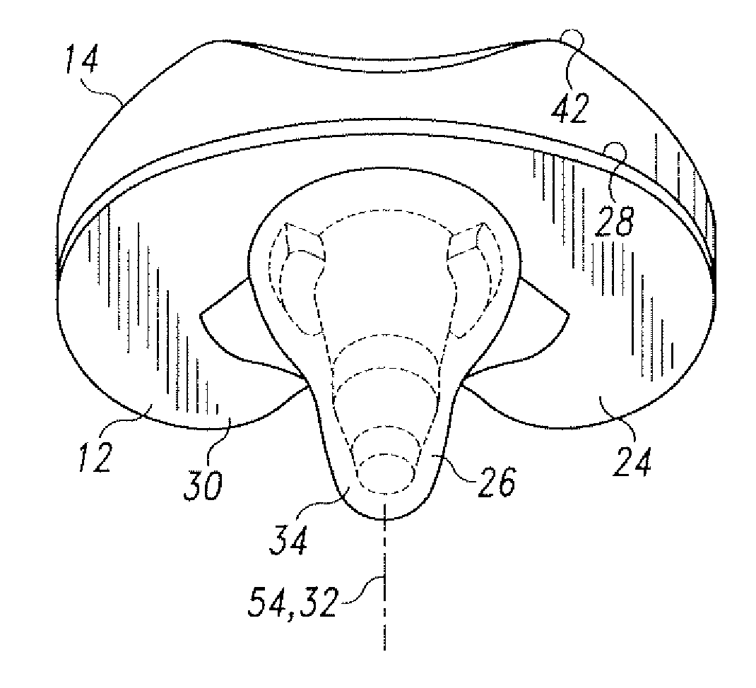
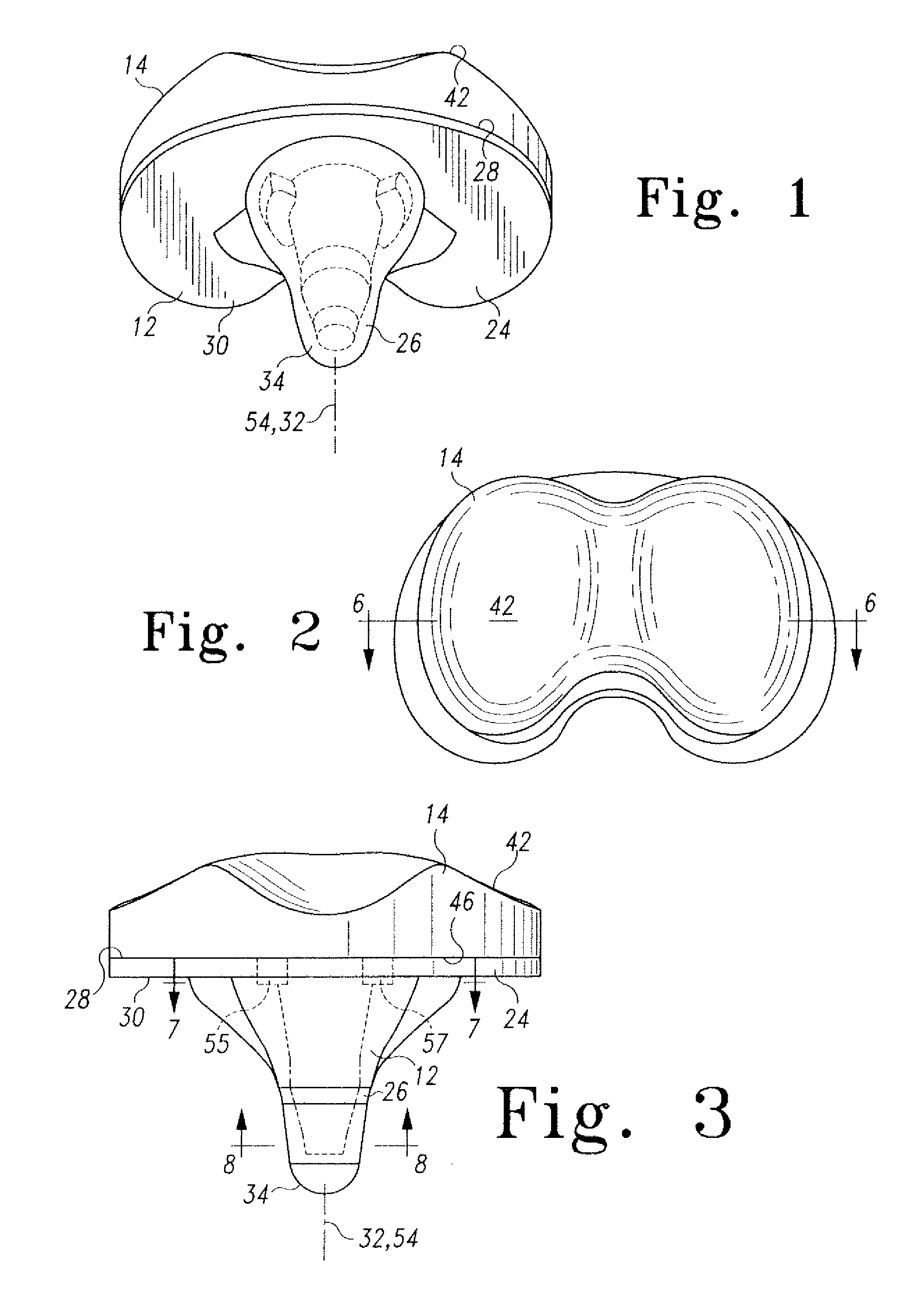
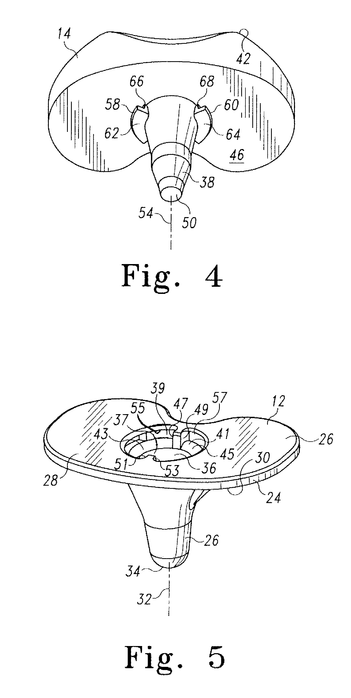
[0033] The present invention provides a prosthetic knee system that includes a femoral implant component 10 (illustrated in FIG. 13), a common tibial base component 12 (illustrated in FIGS. 1-3, 5-8 and 10-12), and interchangeable bearing components 14, 16 that can each be selectively assembled with the common tibial base component 12. The first bearing a component 14 is a fixed bearing component; the second bearing component 16 is a mobile bearing component.

[0034] The femoral component 10 of FIG. 13 includes two convex bearing surfaces 18, 20. The femoral component 10 may be made of standard materials such as a cobalt-chrome alloy or a titanium alloy and may include standard features for such femoral implants. For example, the bone-facing portion 22 may be porous for bone ingrowth or may have recesses to enhance cemented fixation. The invention is not limited to any particular type of femoral component or to any particular feature unless expressly called for in the claims.

[0035] ...


PUM


Abstract

A knee prosthetic system includes a femoral component, a fixed tibial bearing component, a mobile tibial bearing component and an integrated or common tibial base component. The same tibial base component can be used with either the fixed tibial bearing component or the mobile tibial bearing component. The fixed bearing component and tibial base component have mating anti-rotation features. One embodiment of the mobile bearing component does not engage the anti-rotation feature of the tibial base component. Another embodiment engages the anti-rotation feature to allow for limited rotation.

Description

CROSS-REFERENCE TO RELATED APPLICATIONS [0001] Priority is claimed to the following application: U.S. Provisional Patent Application Ser. No. 60 / 732,000 entitled, “MODULAR FIXED AND MOBILE BEARING PROSTHESIS SYSTEM,” filed on Oct. 31, 2005 by Adam I. Hayden and Luke J. Aram, (Docket No. DEP5602USPSP ).FIELD OF THE INVENTION[0002] This invention relates generally to prostheses for human body joints, and more particularly, to prostheses for human knees. BACKGROUND OF THE INVENTION [0003] When a human skeletal joint is damaged, whether as a result of an accident or illness, a prosthetic replacement of the damaged joint may be necessary to relieve pain and to restore normal use to the joint. Typically the entire joint is replaced by means of a surgical procedure that involves removal of the ends of the corresponding damaged bones and replacement of these ends with prosthetic implants. This replacement of a native joint with a prosthetic joint is referred to as a primary total-joint arth...

Claims


Application Information

Patent Timeline
Patent Type & Authority Applications(United States)
IPC IPC(8): A61F2/38
CPCA61F2/3868A61F2/389A61F2002/30329A61F2002/30336A61F2002/30604A61F2002/30614A61F2002/30616A61F2220/0025A61F2220/0033
Inventor ARAM, LUKE J.HAYDEN, ADAM I.
Owner DEPUY (IRELAND) LTD
Learn More