Premix burner with staged liquid fuel supply and also method for operating a premix burner

a liquid fuel supply and burner technology, applied in the direction of burners, combustion types, combustion processes, etc., can solve the problems of low penetration capability of the longitudinal feed of the fuel feed to the air inlet slots, high turbine exhaust temperature, and local material overheating on the partial cone shells themselves, so as to reduce the emission of nitrogen oxide and avoid thermoacoustic vibrations

Active Publication Date: 2007-05-03
ANSALDO ENERGIA SWITZERLAND AG
View PDF4 Cites 20 Cited by
  • Summary
  • Abstract
  • Description
  • Claims
  • Application Information

AI Technical Summary

Benefits of technology

[0011] A premix burner is disclosed with staged liquid fuel supply with at least two partial cone shells, which on the radial side form the boundary of a swirl chamber which axialwards conically widens. A premix burner, which is operable with liquid fuel, can be operated in a staged mode of operation, i.e. to operate individually with liquid fuel both a fuel feed thro

Problems solved by technology

On the other hand, if the dwell time of the fuel inside the combustion chamber is constantly smaller than the time span inside which the rest of the fuel feed phases are forming, then the combustion takes place in the course of a diffusion, as result of which ultimately high portions of nitrogen oxide are released and, furthermore, high turbine exhaust temperatures occur.
However, the only s

Method used


Image

  • Premix burner with staged liquid fuel supply and also method for operating a premix burner
  • Premix burner with staged liquid fuel supply and also method for operating a premix burner
  • Premix burner with staged liquid fuel supply and also method for operating a premix burner

Examples


Embodiment Construction

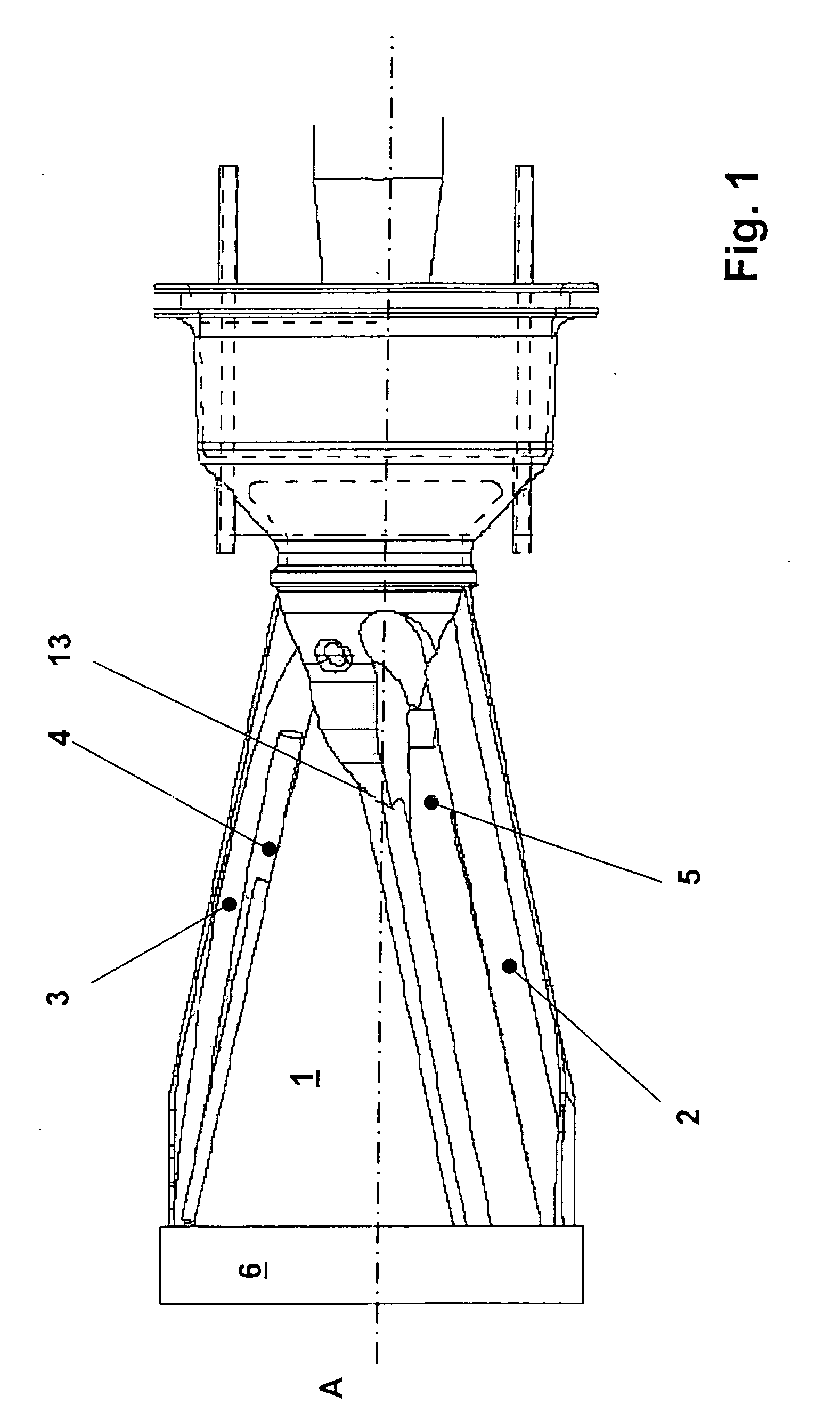
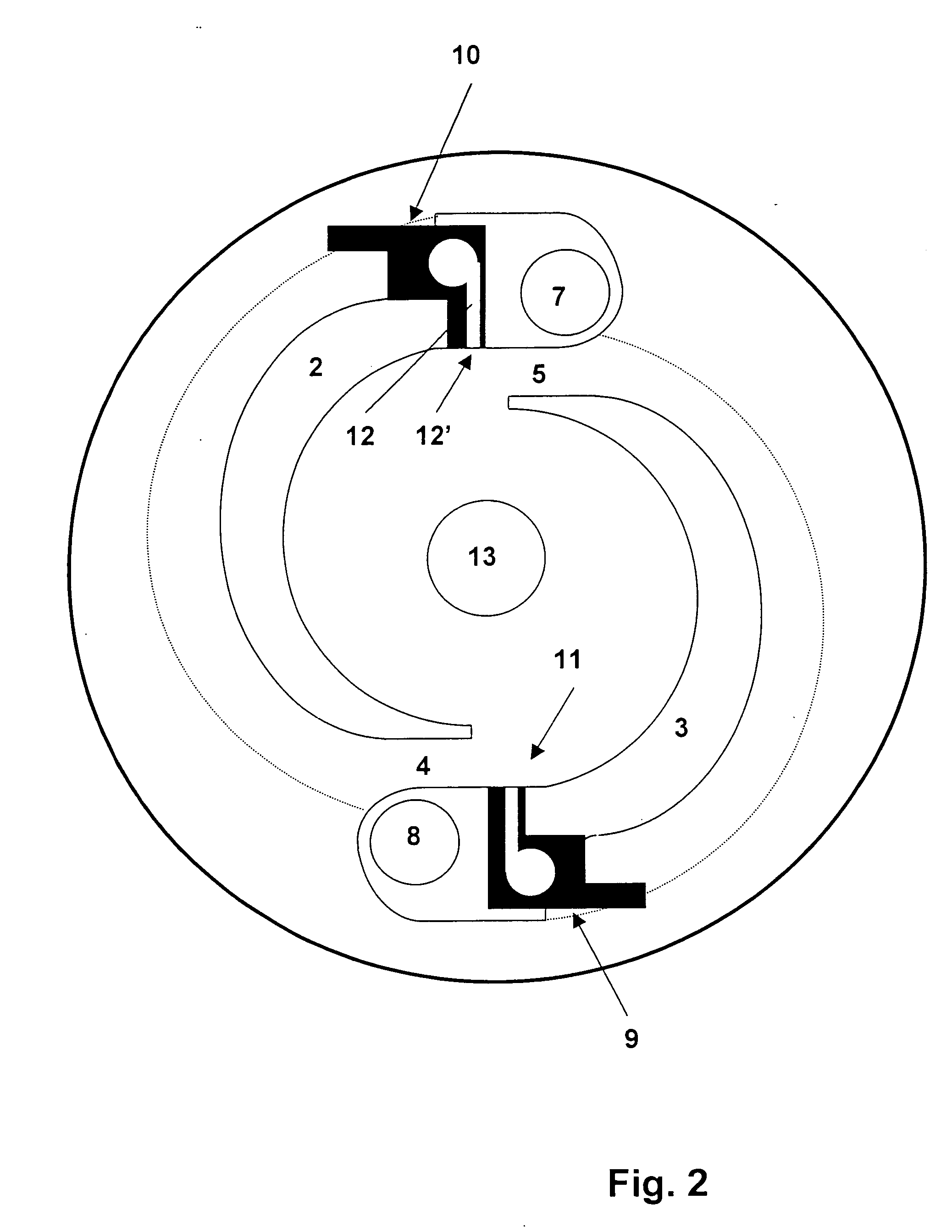
[0021] For the description of the exemplary cone-form premix burner shown in FIG. 1, which is shown in side view presentation, refer also to the cross sectional view according to FIG. 2. Without further differentiation between FIG. 1 and FIG. 2, reference is made to both figures in the following.

[0022] Thus, the premix burner which is shown has a swirl chamber 1, axialwards conically widening, which is radially bounded by two partial cone shells 2, 3. The partial cone shells 2, 3 are arranged in a partially interlocking manner, and by their tangentially extending side edges enclose two air inlet slots 4, 5. Combustion air enters tangentially into the swirl chamber 1 through the air inlet slots 4, 5 which lie symmetrically opposite with regard to the center axis A, and propagates inside the swirl chamber axialwards as a conically expanding swirled flow. The flow characteristic of the swirled flow which forms inside the swirl chamber 1 is determined basically by the clear width of th...


PUM


Abstract

A premix burner with staged liquid fuel supply is described having at least two partial cone shells which on the radial side form the boundary of a swirl chamber which axialwards conically widens, which partial cone shells are arranged in a partially overlapping manner, the center axes of the partial cone shells of which extend with offset effect in relation to each another, and the mutually overlapping partial cone shell sections of which enclose in each case an air inlet slot which extends tangentially to the swirl chamber, with a burner lance which projects axialwards into the swirl chamber, which lance provides means for feed of liquid fuel into the swirl chamber, and also with further means for feed of liquid fuel which are provided in the region of the air inlet slots. As such, additional means for feed of liquid fuel along at least one air inlet slot are formed and arranged in such a way that the liquid fuel delivery, which is conditioned by the further means, takes place in the form of a fuel spray which propagates perpendicularly to the tangential longitudinal extent of the air inlet slot, and also a fuel spray which propagates perpendicularly to an air flow which is directed through the air inlet slot.

Description

CROSS REFERENCE TO RELATED APPLICATIONS [0001] This application claims priority under 35 U.S.C. §119 to Swiss application 0972 / 04 filed in Switzerland on 8 Jun. 2004, and as a continuation application under 35 U.S.C. §120 to PCT / EP2005 / 052315 filed as an International Application on 19 May 2005 designating the U.S., the entire contents of which are hereby incorporated by reference in their entireties.FIELD [0002] A premix burner is disclosed with staged liquid fuel supply with at least two partial cone shells which on the radial side form the boundary of a swirl chamber which axialwards conically widens, which partial cone shells are arranged in a partially overlapping manner, the center axes of the partial cone shells of which extend with an offset effect in relation to each another, and the mutually overlapping partial cone shell sections of which enclose in each case an air inlet slot which extends tangentially to the swirl chamber, with a burner lance which projects axialwards i...

Claims


Application Information

Patent Timeline
IPC IPC(8): F23D14/62F23D11/40F23D14/02F23D17/00F23R3/28F23R3/36
CPCF23C2900/07002F23D11/402F23D14/02F23D17/002F23R3/286F23R3/36
Inventor FLOHR, PETEROOMENS, GIJSBERTUSZAJADATZ, MARTIN
Owner ANSALDO ENERGIA SWITZERLAND AG
Why Eureka
Try Eureka