
Horizontal spool for direct needle closing

Inactive Publication Date: 2007-05-03
SIEMENS VDO AUTOMOTIVE CORP
View PDF5 Cites 19 Cited by
  • Summary
  • Abstract
  • Description
  • Claims
  • Application Information

AI Technical Summary

Benefits of technology

[0010] The direct needle control valve provides for the durable actuation of the needle valve without substantial interference caused by the axial movement of the intensifier and the needle valve during operation.

Problems solved by technology

The selective communication of fuel pressure to the top of the needle valve results in the balance or imbalance of fuel pressures on the needle valve.

Method used


Image

  • Horizontal spool for direct needle closing
  • Horizontal spool for direct needle closing
  • Horizontal spool for direct needle closing

Examples


Embodiment Construction

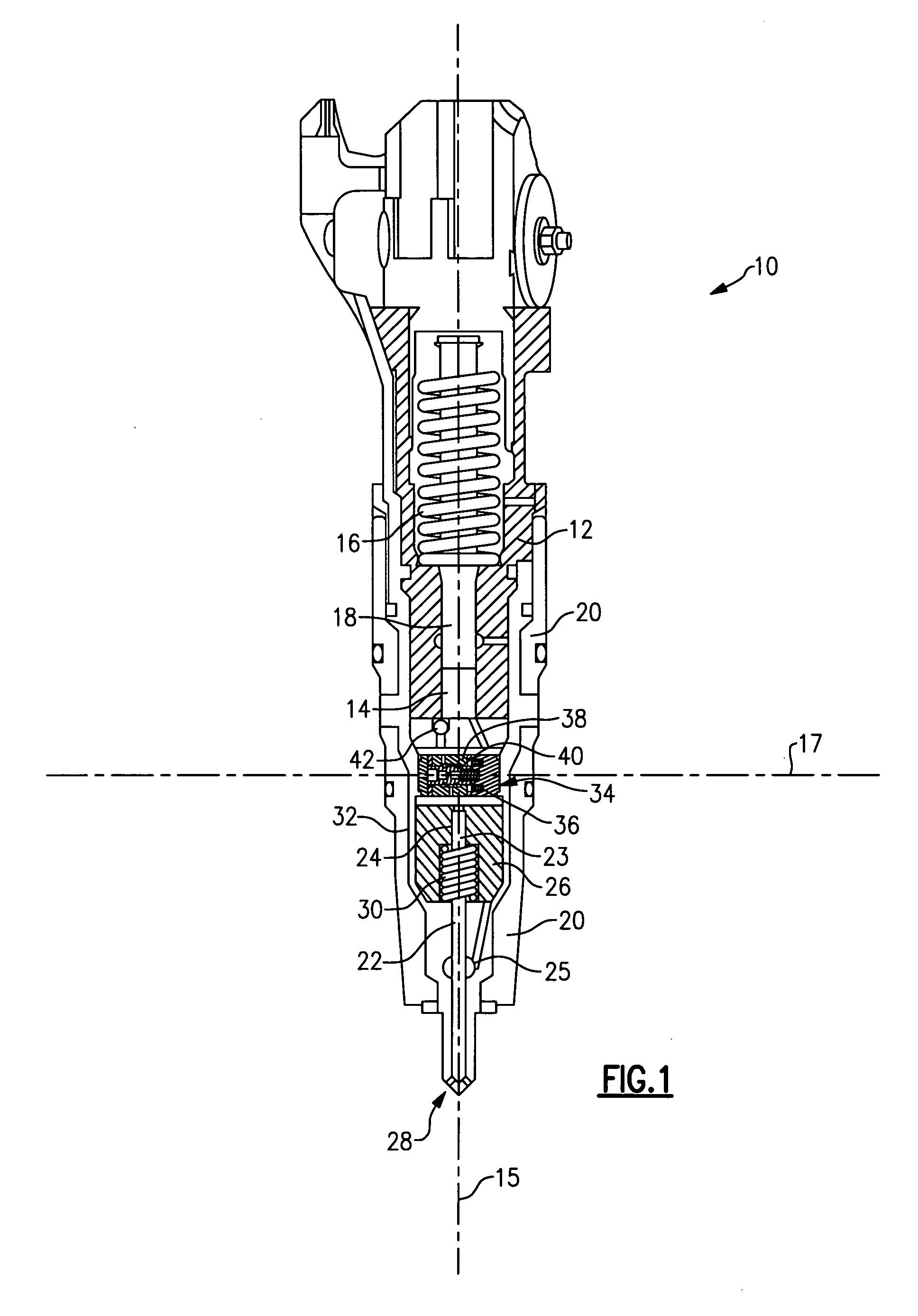
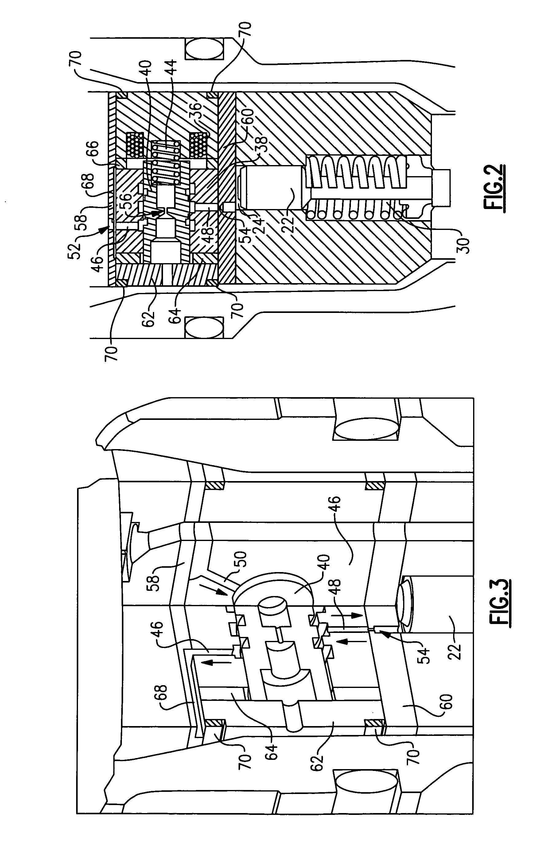
[0015] Referring to FIG. 1, an example fuel injector assembly 10 includes an intensifier body 12 that defines an intensifier bore 14 within which an intensifier piston 18 moves along a longitudinal axis 15. A sleeve 20 is attached to the intensifier body 12 and defines a high-pressure fuel passage 25 from the intensifier bore 14 to an outlet 28. The sleeve 20 also holds a needle valve body 26. The needle valve body 26 defines a needle valve bore 24 within which a needle valve 22 moves. The needle valve 22 moves between an open position that allows high-pressure fuel to exit the outlet 28, and a closed position where no fuel is allowed to exit the outlet 28.

[0016] Movement of the needle valve 22 is controlled by regulating a pressure differential about a head 23 of the needle valve 22. The needle valve is biased by a spring 30 towards the closed position. Fuel pressure on either side of the head 23 of the needle valve 22 provides for the selective opening and closing of the needle v...


PUM


Abstract

A fuel injector assembly includes an intensifier piston and a spool valve that are movable along a first axis. The needle valve is controlled by a needle control valve that includes a spool that moves in a direction transverse to movement along the first axis.

Description

CROSS REFERENCE TO RELATED APPLICATION [0001] The application claims priority to U.S. Provisional Application No. 60 / 727,935 which was filed on Oct. 18, 2005.BACKGROUND OF THE INVENTION [0002] This invention generally relates to valve assembly for actuating a needle valve. More particularly, this invention relates to a spool valve actuateable for opening and closing a fuel injector needle valve. [0003] A fuel injector for a vehicle provides for the selective injection of fuel into a combustion chamber. The fuel injector typically includes a needle valve that opens and closes to control the flow of fuel into the combustion chamber. Opening and closing of the fuel injector is timed with the combustion cycle of the engine and therefore speeds up or slows down depending on engine speed. The needle valve is desired to open and close quickly to facilitate properly timed injection of fuel. [0004] A conventional fuel injector includes a spool valve movable parallel to the opening and closin...

Claims


Application Information

Patent Timeline
IPC IPC(8): F02M41/16
CPCF02M47/027F02M57/02F02M57/023F02M63/0015F02M63/004F02M63/0045F02M2200/28
Inventor WISDOM, BEN
Owner SIEMENS VDO AUTOMOTIVE CORP
Learn More