
Input device

a technology of input device and input input, which is applied in the field of input device, can solve problems such as difficulty in performing a reliable input operation

Inactive Publication Date: 2006-01-26
PANASONIC CORP
View PDF10 Cites 17 Cited by
  • Summary
  • Abstract
  • Description
  • Claims
  • Application Information

AI Technical Summary

Benefits of technology

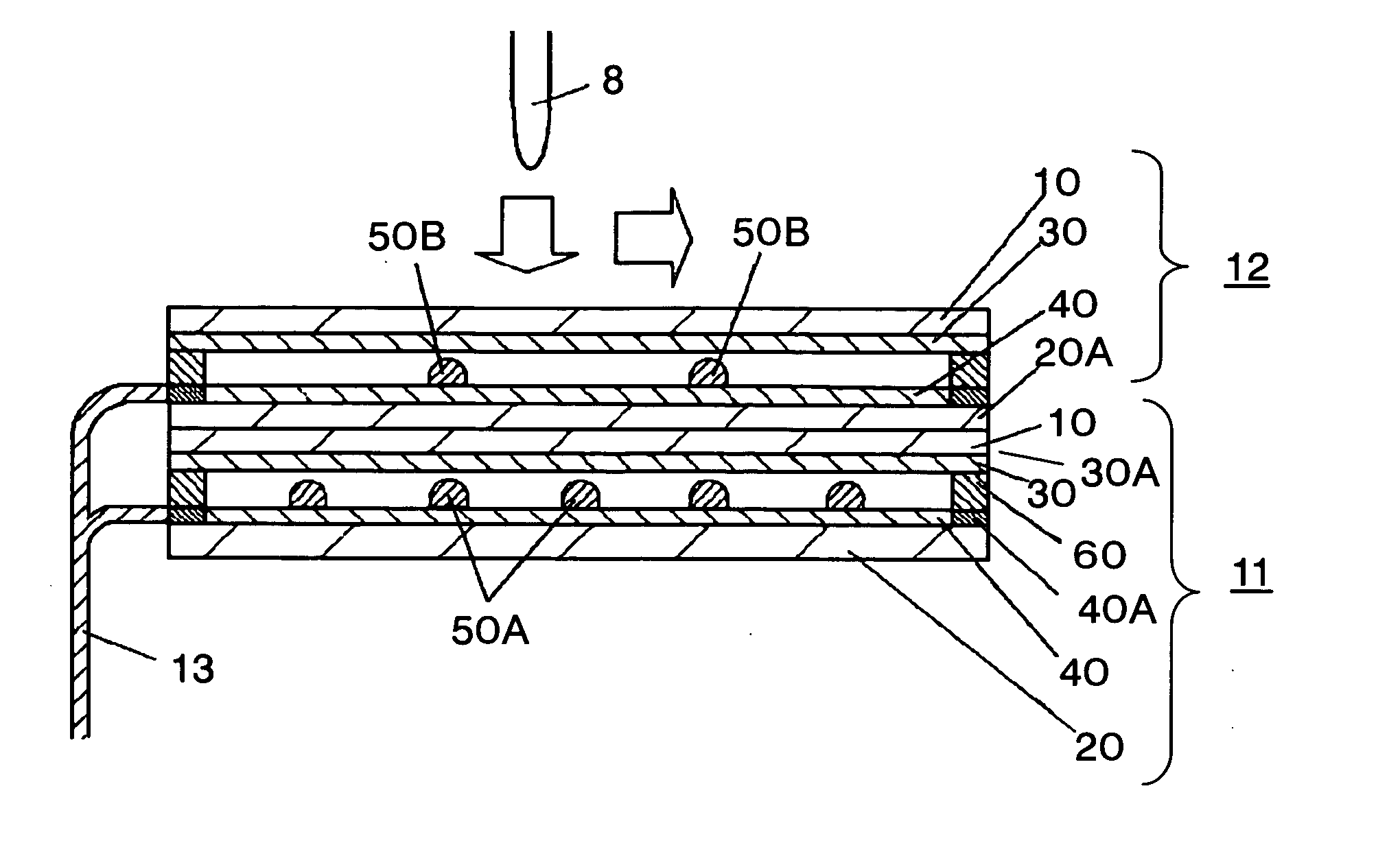
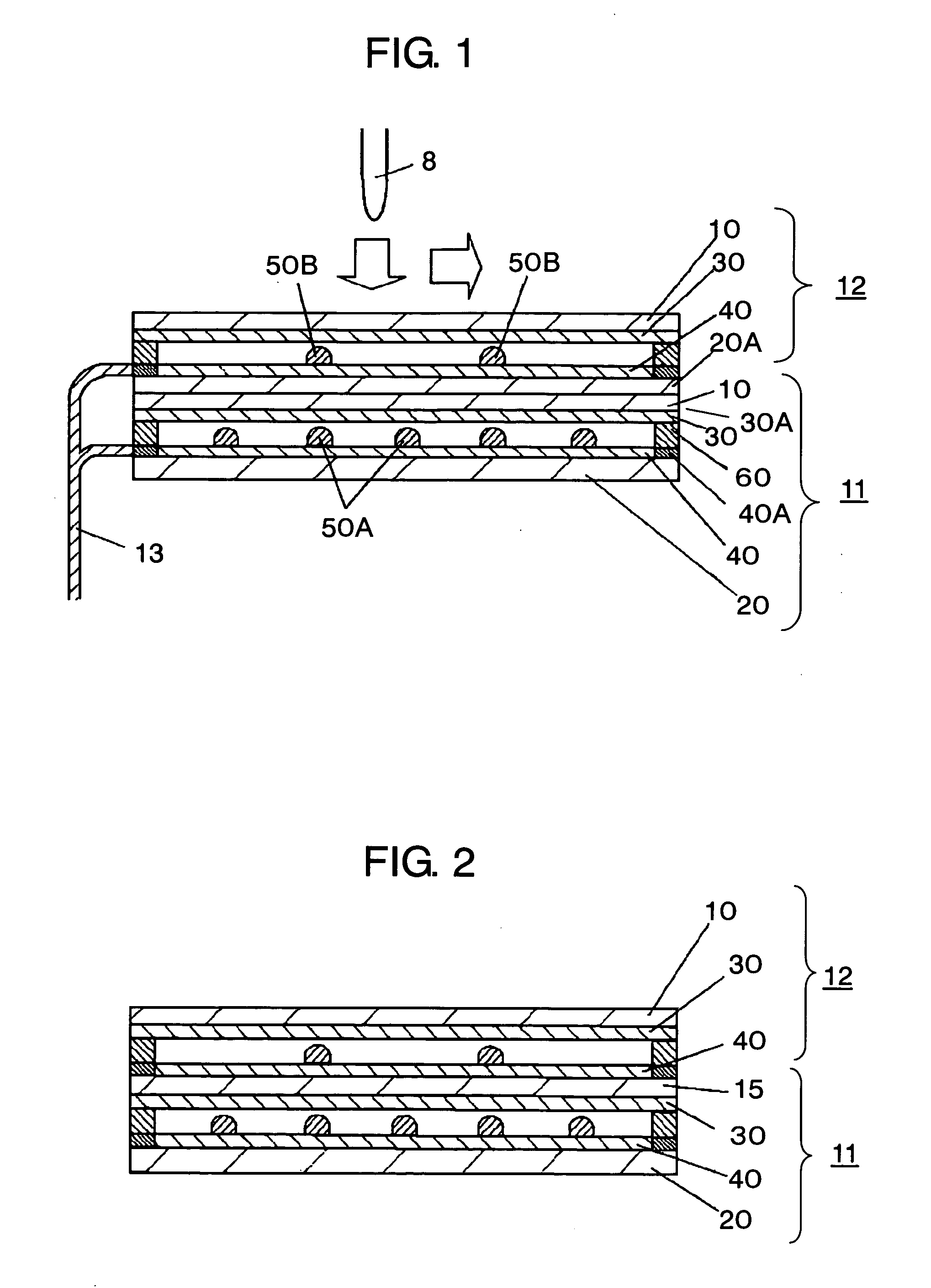
[0014] The present invention provides an input device made up of a plurality of touch panels piled on top of another, each touch panel having an upper conductive layer on an upper substrate and a lower conductive layer on a lower substrate arranged to oppose each other at a predetermined distance. Hence, after a menu item has been selected or a character has been drawn on the upper touch panel, if a stronger push is given to the upper touch panel, the item or character is determined by the lower touch panel without the need for tilting the touch panel downward. Thus, an input device capable of making reliable actuation free from an operating error can be realized.

Problems solved by technology

Accordingly, there has been a problem that an operating error of the push switch is liable to occur depending on the position on which the pushing force is exerted and hence it becomes difficult to perform a reliable inputting operation.

Method used


Image

  • Input device
  • Input device
  • Input device

Examples


exemplary embodiment

[0023] (Exemplary Embodiment)

[0024] In FIG. 1, upper substrate 10 in a film form and light transmissive is made of polyethylene terephthalate (PET), polyether sulfone, polycarbonate (PC), norbornene resin, or the like.

[0025] Light-transmitting lower substrate 20 is similarly made of light-transmitting glass, acrylic resin, or the like. All over the bottom face of upper substrate 10, there is provided light-transmitting upper conductive layer 30 made of ITO, tin oxide, or the like, while all over the top face of lower substrate 20, there is provided similarly light-transmitting lower conductive layer 40, both layers being formed by sputtering or the like.

[0026] On the top face of lower conductive layer 40, there are disposed a plurality of dot spacers 50A made of such an insulating resin as epoxy resin or silicone resin at a predetermined interval. Further, at both front and rear ends of upper conductive layer 30, there are formed a pair of upper electrodes 30A. On both left and ri...


PUM


Abstract

An input device is provided by piling up a plurality of touch panels in which an upper conductive layer of an upper substrate and a lower conductive layer of a lower substrate are disposed to oppose each other with a predetermined distance therebetween. Thus, inputting operations such as selection of a menu item or drawing of a character and determination of the item or character can be performed without tilting the input device downward but keeping it stationary and, hence, reliable actuation free from operating error can be attained.

Description

FIELD OF THE INVENTION [0001] The present invention relates primarily to an input device used for operating various pieces of electronic equipment. BACKGROUND OF THE INVENTION [0002] Advancements in performance and diversification in application of electronic apparatuses such as portable telephones and personal digital assistants are being made these days. Keeping pace with the advancements, devices having a light transmitting touch panel mounted on the front face of a display unit of a liquid crystal display (LCD) or the like and allowing functions of an apparatus to be switched over from one to another are increasing in number. In the above device, the switching between various functions is performed by user's pushing on the touch panel with a finger or pen while visually recognizing, through the touch panel, a display on the display unit behind the touch panel. Thus, there are demands for input devices that can be operated with ease and free of operating error. [0003] An example ...

Claims


Application Information

Patent Timeline
Patent Type & Authority Applications(United States)
IPC IPC(8): G09G5/00
CPCG06F3/045
Inventor FUKUI, TOSHIHARUKUSUNOKI, HISANORINAKANISHI, AKIRAMURAKAMI, TETSUO
Owner PANASONIC CORP
Learn More