Belt wheel capping system

a technology of belt wheels and capping systems, which is applied in the direction of caps, rotating screw stopper insertion, applications, etc., can solve the problems of complex capping heads, and achieve the effect of improving throughpu

Inactive Publication Date: 2007-05-03
NATIONAL INSTRUMENTS
View PDF11 Cites 16 Cited by
  • Summary
  • Abstract
  • Description
  • Claims
  • Application Information

AI Technical Summary

Benefits of technology

[0038] In accordance with the above objects, an improved high-throughput system for screw-capping a continuous supply of bottles with a continuous supply of screw-caps is disclosed. The belt-wheel capping system generally comprises a conveyor having opposed parallel gripper belts for ushering bottles single-file along a continuous supply and transporting them to a capping station for screw-capping (the spacing of said gripper belts being adjustable to accommodate bottles of various sizes), an adjustable-incline pivoting cap feeding chute for delivery of caps to the capping station, a capping head for receiving bottles and caps from said conveyor and feeding chute, respectively, and for applying the caps onto the bottles with programmable torque. The capping head is fully adjustable and further comprises an enclosure, a programmable logic controller (PLC) for controlling operation of the entire capping system, a capping head roller carriage defining at least one bay for insertion of a roller assembly, a roller assembly inserted into the bay and including a motor and clutch adapted to drive at least one capping head roller with adjustable torque, a pair of dual-gripper belt cassettes each comprising a counter-rotating double-belt suspended beneath the capping head for controlling bottles at the capping station, and an adjustable cap feed stabilizer assembly for guiding the infeed of caps from the inclined chute to the capping head. In addition, a plurality of indexed readouts for calibration are provided at all primary adjustment points. In conjunction with the digital readouts, the programmable logic controller (PLC) is programmed to provide a user interface with a series of guidance menus to guide a technician through the changeover process, step-by-step identifying a component to be adjusted and providing a calibrated adjustment value to the technician. This configuration improves throughput and makes changeovers between production runs (of different bottles and caps) as effortless as possible.

Problems solved by technology

Unfortunately, the capping heads can be complex, utilizing magnetic clutch(es) that may be adjusted for torque adjustment.

Method used


Image

  • Belt wheel capping system
  • Belt wheel capping system
  • Belt wheel capping system

Examples


Embodiment Construction

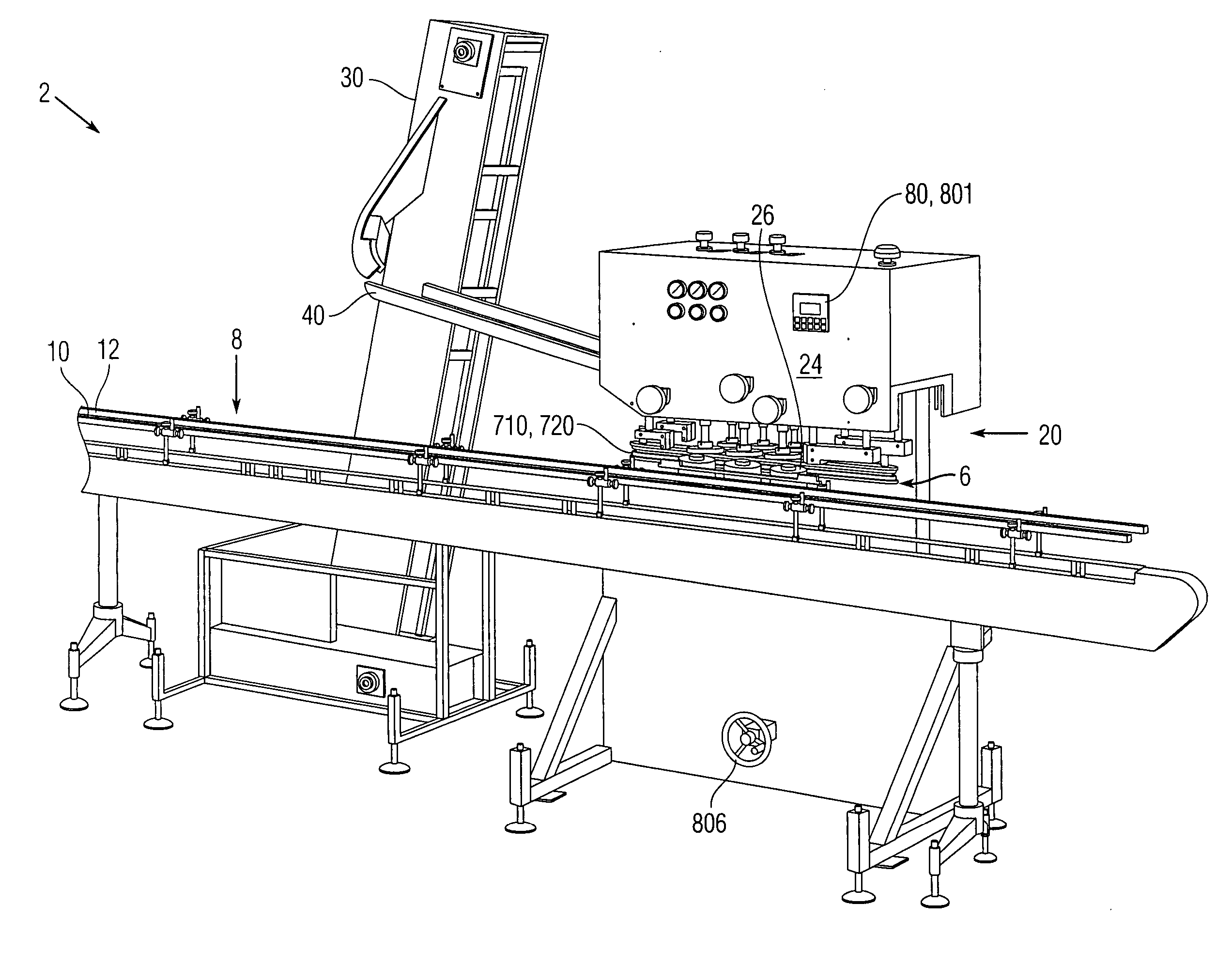
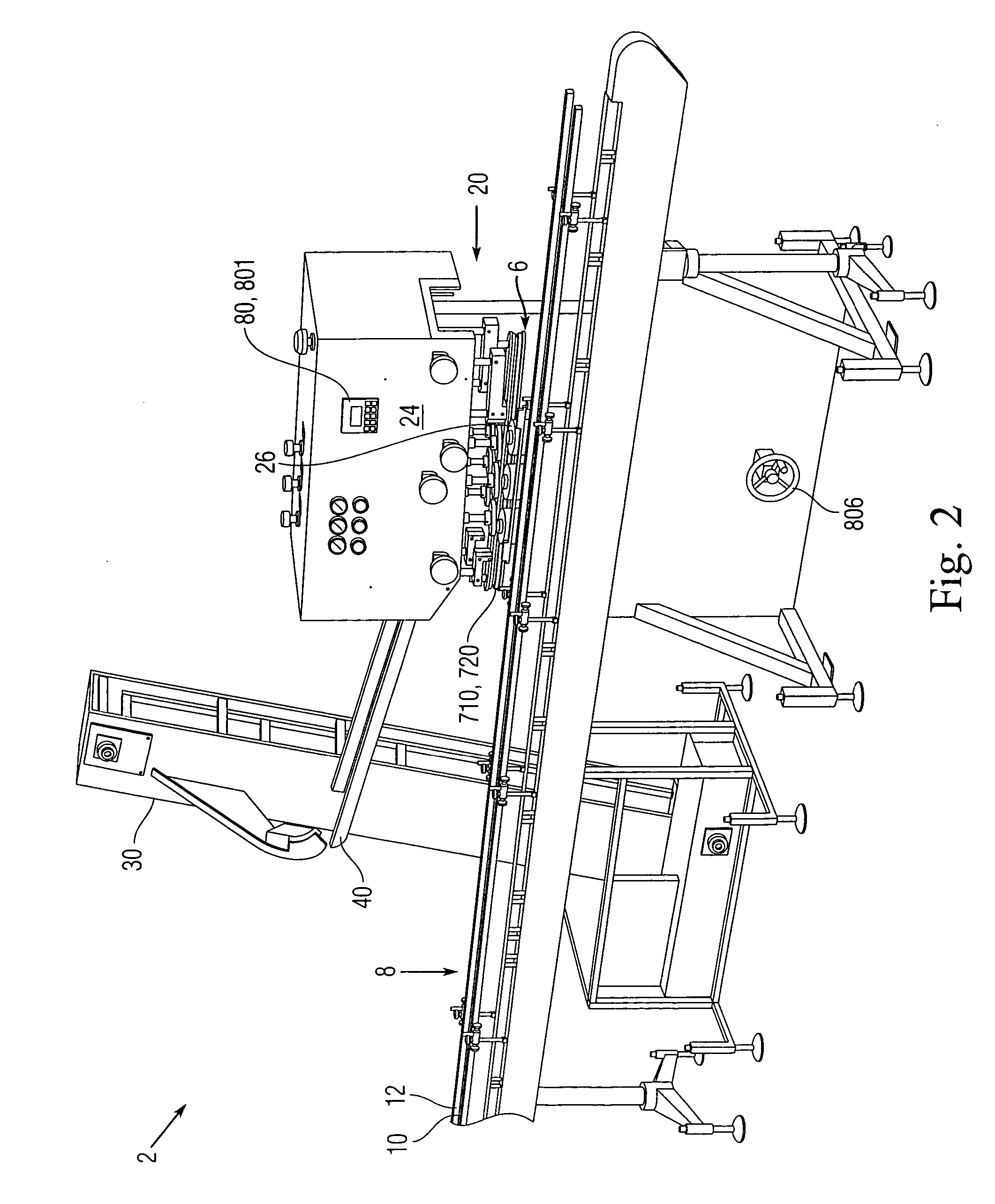
[0056] The present invention is an improved system for screw-capping a continuous supply of bottles with a continuous supply of screw-caps using a “belt wheel” type capping head. The bottles are conveyed to the capping head on a conveyor comprising a horizontal moving belt flanked by guide rails. Bottles are seated atop the conveyor single-file and, guided by the guide rails, are moved single-file along in a continuous supply to a capping station. Concurrently, an elevator raises caps from a hopper filled with caps, and delivers them via a cap feeding chute to the capping station. The caps are engaged and screwed onto the bottles with adjustable torque. The components of the capping system as a whole, and the capping station in particular, are fully adjustable in various respects (to be described) to accommodate caps and bottles of widely varying sizes and shapes, thereby allowing a broader variation in all respects when compared to the prior art. Moreover, the present system improv...


PUM


Abstract

An improved high-throughput system for screw-capping a continuous supply of bottles with a continuous supply of screw-caps. The system generally comprises a conveyor having opposed parallel gripper belts for ushering bottles single-file along a continuous supply and transporting them to a capping station for screw-capping (the spacing of said gripper belts being adjustable to accommodate bottles of various sizes), an adjustable-incline cap feeding chute for delivery of caps to the capping station, a capping head for receiving bottles and caps from said conveyor and feeding chute, respectively, and for applying the caps onto the bottles with programmable torque. The capping head is fully adjustable and comprises a programmable logic controller (PLC) for controlling operation of the entire capping system. Indexed readouts for calibration are provided at all primary adjustment points. In conjunction with the digital readouts, the programmable logic controller (PLC) is programmed to provide a user interface with a series of guidance menus to guide a technician through the changeover process, step-by-step identifying a component to be adjusted and providing a calibrated adjustment value to the technician. This configuration improves throughput and makes changeovers between runs (of different bottles and caps) as effortless as possible.

Description

CROSS-REFERENCE TO RELATED APPLICATIONS [0001] The present application derives priority from U.S. Provisional application No. 60 / 719,805 filed Sep. 23, 2005.BACKGROUND OF THE INVENTION [0002] 1. Field of the Invention [0003] The present invention relates to automated high-volume capping of bottles and containers and, more particularly, to an improved high-throughput system for screw-capping a continuous supply of bottles with a continuous supply of screw-caps. [0004] 2. Description of the Background [0005] The filling and capping process generally entails supplying bottles, containers, or cases containing bottles / containers along a conveyor, automatically filling them at a filling station, and automatically capping them at a capping station. Various testing and control functions may be performed along the way, for instance, testing and control of fill volume, cap torque, conveyor velocity, etc. The apparatus which performs the process must be capable of accommodating a wide variety ...

Claims


Application Information

Patent Timeline
Patent Type & Authority Applications(United States)
IPC IPC(8): B67B3/20
CPCB67B3/2046
Inventor PERAZZO, NICHOLAS J.VANDEGEIJN, PETER THEODOR
Owner NATIONAL INSTRUMENTS
Why Eureka
Try Eureka