
Relay-fuse system and method thereof

Inactive Publication Date: 2007-04-26
FORD DOUGLAS K +1
View PDF23 Cites 8 Cited by
  • Summary
  • Abstract
  • Description
  • Claims
  • Application Information

AI Technical Summary

Benefits of technology

[0008] In view of the foregoing disadvantages inherent in the above mentioned prior arts, the general purpose of the present invention is to provide a relay-fuse system which include all the advantages of the prior arts, and to overcome the abovementioned drawbacks of the prior art. The present invention provides a relay-fuse system which comprises a fuse attached to a relay, such that, the fuse is in electrical engagement with the electrical current passing through high voltage contacts of the relay and increases the over all AIC rating of the relay.
[0009] In one aspect, the present invention provides a new, simplified, and efficient relay-fuse system which provides a relay with an AIC rating for greater number of actuations and eliminates the need for circuit breaker. The relay-fuse system of the present invention can be mass produced inexpensively.
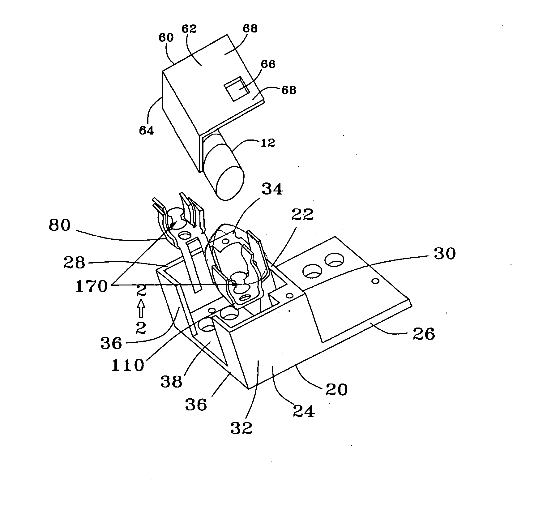
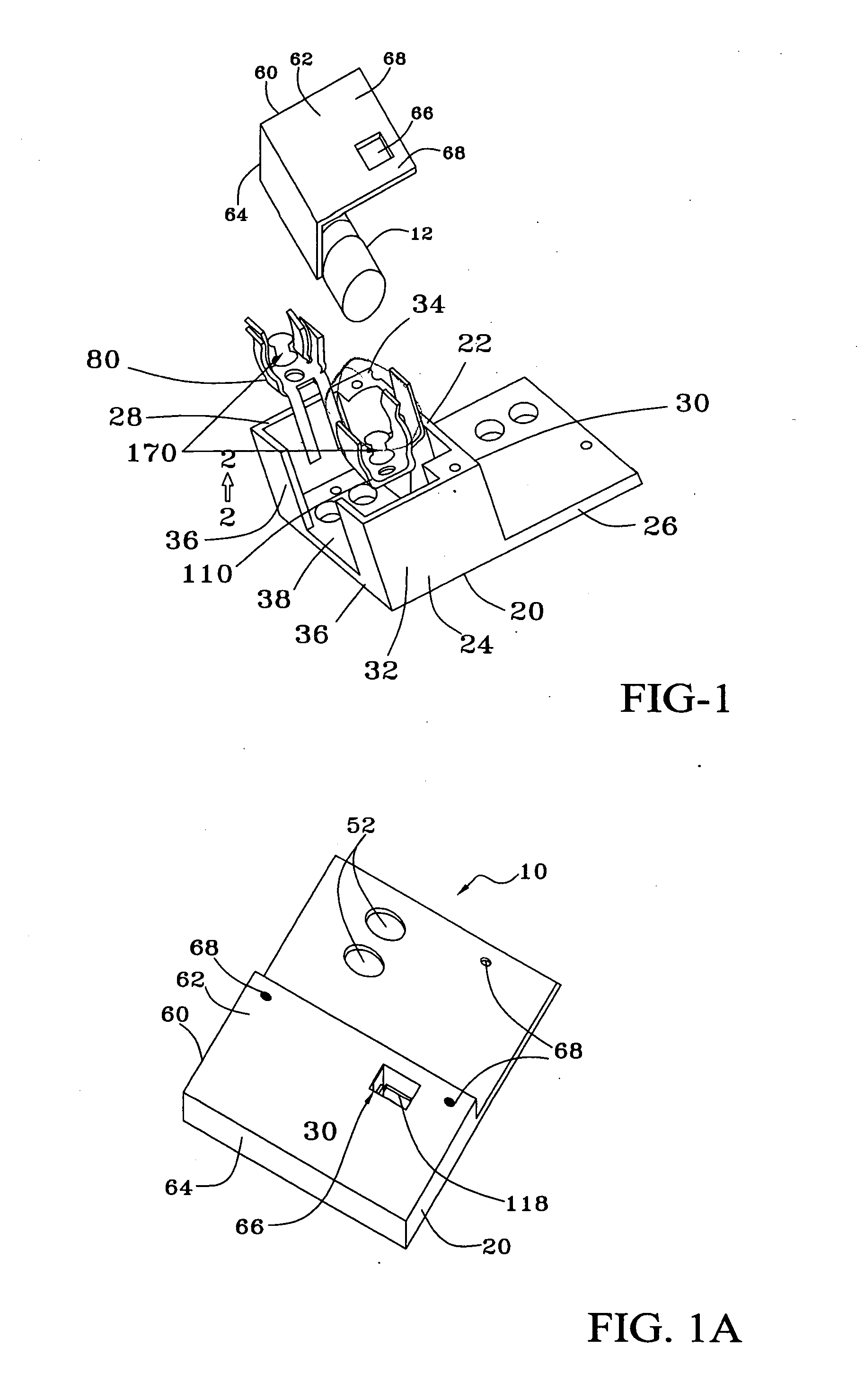
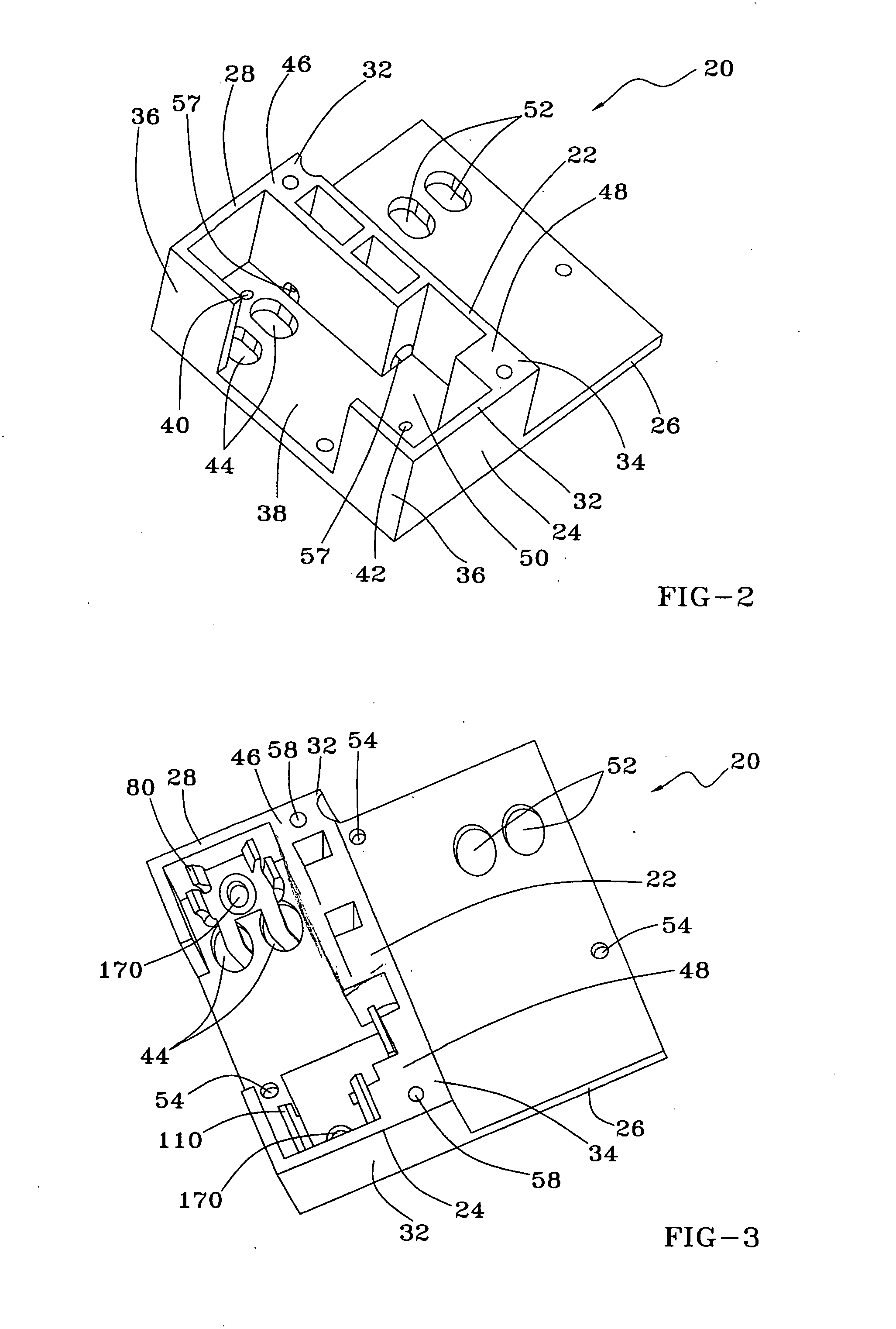
[0011] In another aspect, the present invention provides a relay-fuse system which comprises: a relay having a base member configured to be connected to an electrical device; a fuse assembly mounted on the base member and having a first clip and a second clip capable of electrically engaging a fuse; a fuse carrier member forms a receiving area for receiving the first clip, the second clip, and the fuse; and a cover member mounted on the fuse carrier member for covering the receiving area. The first clip is capable of connecting to the relay; the second clip is capable of connecting to an incoming power line and establishes electrical connection between the incoming power line, the relay fuse system, and the electrical device. The relay fuse system of the present invention increases the overall ampere interrupt current (AIC) rating of the relay.
[0012] In another aspect, the present invention provides a fuse assembly in electrical connection with a relay and an electrical device. The fuse assembly comprises: a fuse, a first clip, a second clip, a fuse carrier member, and a cover member. The fuse has a first electrical contact and a second electrical contact. The first clip has a plurality of first fuse engaging portions and a plurality of legs extending from a base portion in a direction opposite to a direction in which the first fuse engaging portion extend. The first clip further has a first clip opening for receiving a fastener. The second clip has a first base portion extending to form a second base portion, the first base portion has a pair of second fuse engaging portions extending therefrom and a connecting portion extends from the second base portion. The second fuse engaging portions and the connecting portion extends in the same direction. The second clip further has a second clip opening for receiving a fastener. The fuse carrier member configured to form a receiving area for receiving the first clip, the second clip, and the fuse; and a cover member mounted on the fuse carrier member for covering the receiving area. The first clip is capable of connecting to the relay and the second clip is capable of connecting to an incoming power line thereby establishes electrical connection between the incoming power line, the relay fuse system, and the electrical device. The fuse assembly of the present invention increases overall ampere interrupt current (AIC) rating of the relay.

Problems solved by technology

This patent involves a complex configuration and does not address the issue related to the requirements / standard of National Electric Code 2002, for handling, interrupt current ratings.
This patent also involves a complex configuration and does not address the issue related to the requirements / standard of National Electric Code 2002, for handling interrupt current ratings.
None of the prior art discloses any system which aims to make relays compliant with the National Electric Code 2002 requirements / standards for handling interrupt current ratings equivalent to circuit breakers used in any constructed building.

Method used


Image

  • Relay-fuse system and method thereof
  • Relay-fuse system and method thereof
  • Relay-fuse system and method thereof

Examples


Embodiment Construction

[0025] The exemplary embodiments described herein detail for illustrative purposes are subject to many variations in structure and design. It should be emphasized, however that the present invention is not limited to a particular relay-fuse / device system shown and described. Rather, the principles of the present invention can be used with a variety of relay-fuse device / system configurations. It is understood that various omissions, substitutions of equivalents are contemplated as circumstances may suggest or render expedient, but is intended to cover the application or implementation without departing from the spirit or scope of the claims of the present invention.

[0026] The present invention provides a new, simplified, and efficient relay-fuse system which provides a relay for greater number of actuations and eliminates the need for circuit breaker. The relay-fuse system of the present invention can be mass produced inexpensively.

[0027] The present invention make the attachment o...


PUM


Abstract

The present invention provides a relay-fuse system for increasing overall ampere interrupt current (AIC) rating of the relay. The relay fuse system comprises a relay having a base member configured to be connected to an electrical device; a fuse assembly mounted on the base member, the fuse assembly having a first clip and a second clip capable of electrically engaging a fuse; a fuse carrier member configured to form a receiving area for receiving the first clip, the second clip, and the fuse; and a cover member mounted on said fuse carrier member for covering the receiving area. The first clip is capable of connecting to the relay, the second clip is capable of connecting to an incoming power line thereby establishes electrical connection between the incoming power line, the relay fuse system, and the electrical device and increases overall ampere interrupt current (AIC) rating of said relay.

Description

FIELD OF THE INVENTION [0001] The present invention relates to fault tolerant assemblies, and, more particularly, to a system and method of relay-fuse for handling interrupt current ratings equivalent to circuit breakers. BACKGROUND OF THE INVENTION [0002] In an electric power transfer line, a circuit interrupter is required for opening and stopping an overload of electrical current due to any type of electrical fault created by man, machine, mistake or nature. Circuit breakers have been used for performing such circuit interruption functions. Relays were used as an alternative to circuit breakers, since relays were less expensive than circuit breakers and lasted for greater number of actuations than a circuit breaker. The use of relays having a lower ampere interrupt current (AIC) rating has been prohibited due to security reasons and relays with an AIC rating of less than 30000 were disallowed from installation. [0003] The prior art related to the relays for the purpose of control...

Claims


Application Information

Patent Timeline
IPC IPC(8): H05K1/00
CPCH01H9/10H01H85/202H01H85/2045H01R13/111
Inventor FORD, DOUGLAS K.KULKARNI, AMIT
Owner FORD DOUGLAS K
Learn More