
Method of manufacturing thin film transistor including ZnO thin layer

a thin film transistor and zno technology, applied in the field of thin film transistors, can solve the problems of low performance of transistors, large area deposited transparent semiconductor layers, and inability to meet the requirements of high-performance transistors, and achieve low-cost processes, good characteristics, and simple

Inactive Publication Date: 2007-04-26
ELECTRONICS & TELECOMM RES INST
View PDF7 Cites 18 Cited by
  • Summary
  • Abstract
  • Description
  • Claims
  • Application Information

AI Technical Summary

Benefits of technology

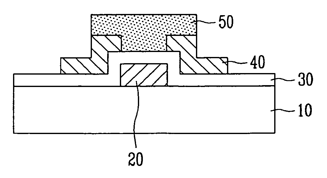
[0010] The present invention is directed to a method of manufacturing a thin film transistor (TFT) including a ZnO thin layer with good characteristics, which is formed at a low temperature through a simple, low-cost process.
[0011] Also, the present invention is directed to a method of manufacturing a flexible transistor array in which a semiconductor layer is formed by a low-temperature process applicable to a plastic substrate, thus resulting in a transistor that is superior to conventional OTFTs or a-Si TFTs in device characteristics and does not deteriorate under external circumstances.
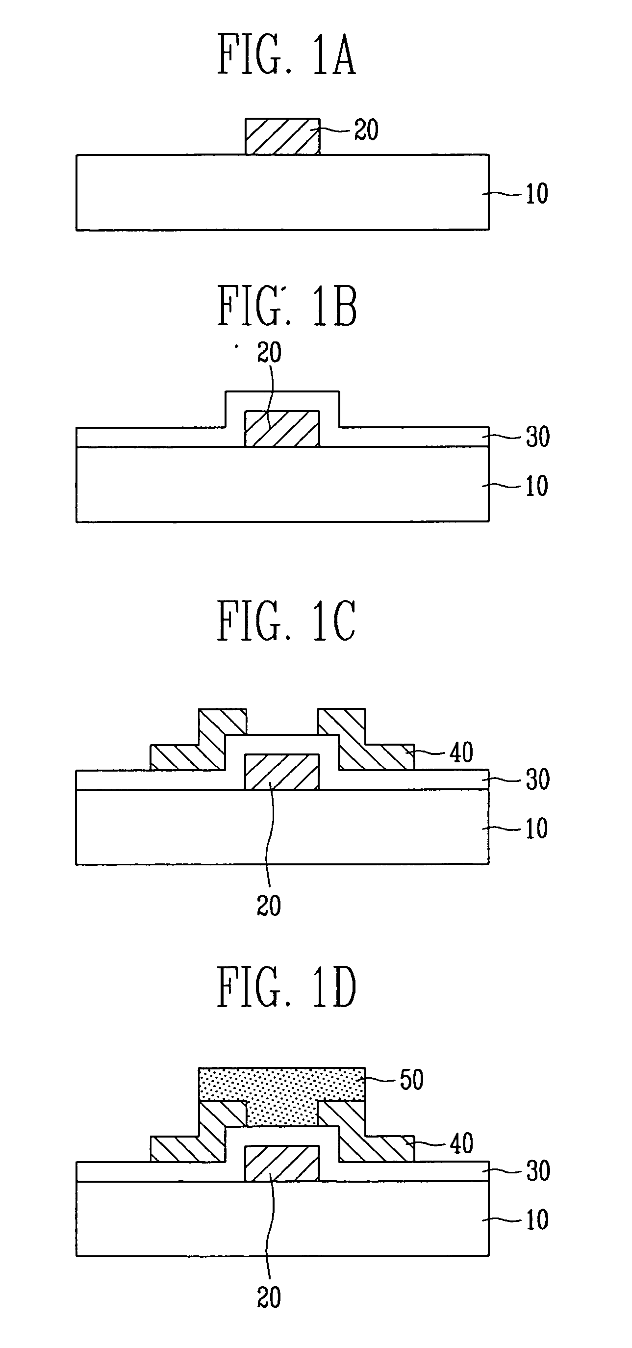
[0022] In order to prevent diffusion of impurities from the substrate into devices, the method may further include the step of forming a buffer insulating layer between the substrate and the gate electrode.

Problems solved by technology

In addition to an amorphous silicon (a-Si) transistor that is in the most common use, laborious research for a polycrystalline silicon (poly-Si) transistor and an organic semiconductor transistor has lately progressed.
Accordingly, it is difficult to deposit the transparent semiconductor layer on a large area, and the resultant transistor is inferior in performance to conventional a-Si transistors.
Further, since the transparent semiconductor layer is made by an expensive process, it cannot fulfill a need for low-cost transistors of the ubiquitous epoch.
However, it is still difficult to apply the OTFT to real devices because the OTFT has bad performance.
Also, since the organic semiconductor deteriorates due to environmental conditions, such as oxygen, water, and heat, it is restricted in life span.
Further, an inorganic transistor based on a plastic substrate has poor device characteristics owing to a low-temperature process, so it cannot be applied to real devices.

Method used


Image

  • Method of manufacturing thin film transistor including ZnO thin layer
  • Method of manufacturing thin film transistor including ZnO thin layer
  • Method of manufacturing thin film transistor including ZnO thin layer

Examples


Embodiment Construction

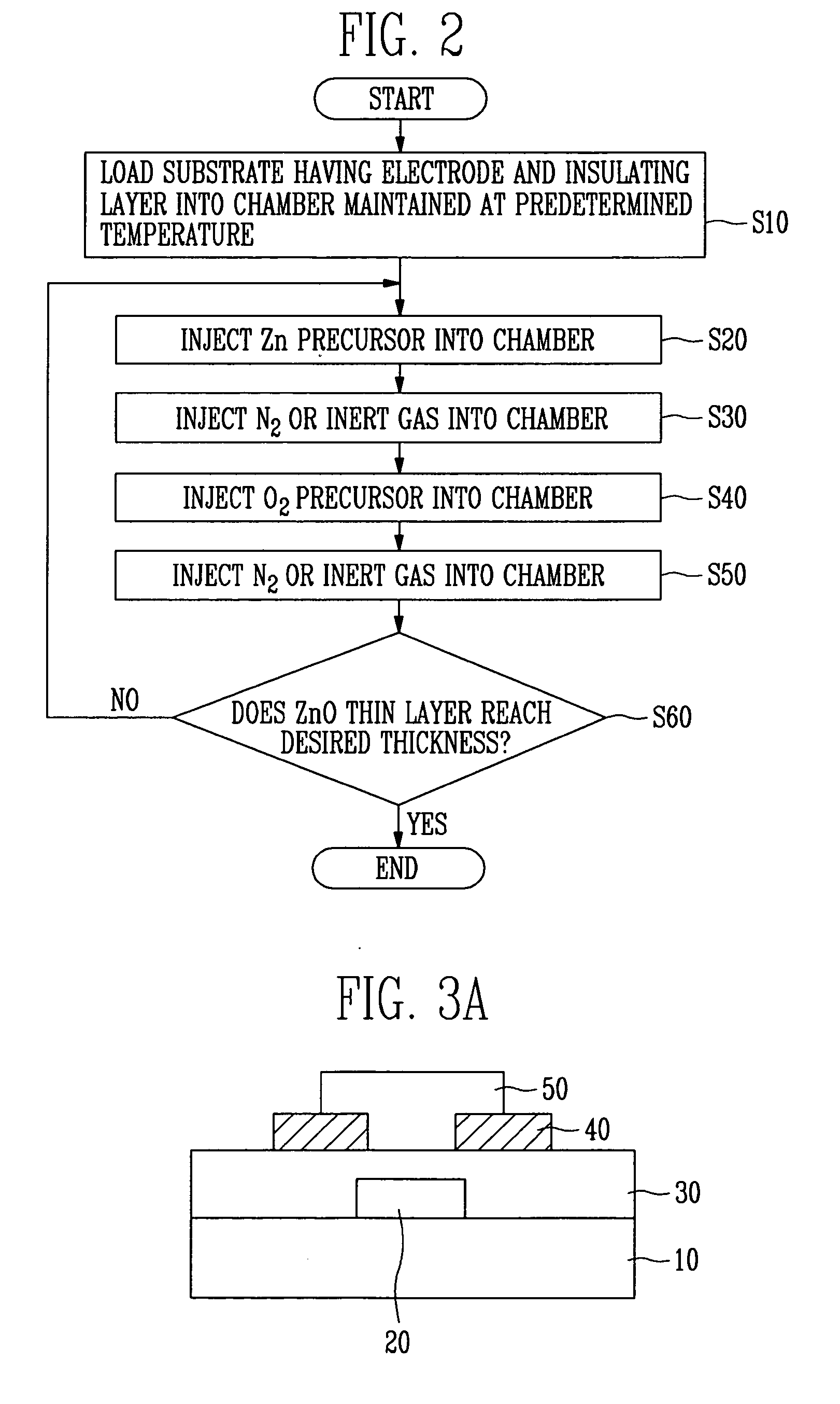
[0044] A method of manufacturing a transistor including a ZnO thin layer grown using an atomic layer deposition (ALD) technique according to the present invention will now be described more fully hereinafter with reference to the accompanying drawings, in which exemplary embodiments of the invention are shown.

[0045] Initially, the ALD technique will be described to facilitate understanding.

[0046] The ALD technique may be greatly classified into a traveling wave reactor type ALD technique and a plasma-enhanced ALD technique.

[0047] More specifically, the plasma-enhanced ALD technique may be divided into a remote plasma ALD technique and a direct plasma ALD technique according to a plasma generator.

[0048] The present invention can employ all kinds of ALD techniques and are not restricted to specific ALD techniques. But, only a process of depositing a ZnO thin layer using a traveling wave reactor type ALD technique will be described in embodiments of the present invention for brevit...


PUM


Abstract

Provided is a method of manufacturing a thin film transistor (TFT) including a transparent ZnO thin layer that is formed at a low temperature by causing a surface chemical reaction between precursors containing elements constituting the ZnO thin layer. The method includes the steps of: depositing a gate metal layer on a substrate and forming a gate electrode using photolithography and selective etching processes; depositing a gate insulator on the substrate having the gate electrode; forming source and drain electrodes; and depositing a ZnO thin layer on the gate insulator using a surface chemical reaction between precursors containing elements constituting the ZnO thin layer.

Description

CROSS-REFERENCE TO RELATED APPLICATION [0001] This application claims priority to and the benefit of Korean Patent Application Nos. 2005-100862, filed Oct. 25, 2005 and 2006-59134, filed Jun. 29, 2006, the disclosures of which are incorporated herein by reference in their entirety. BACKGROUND [0002] 1. Field of the Invention [0003] The present invention relates to a thin film transistor (TFT) including a ZnO thin layer and, more specifically, to a method of manufacturing a TFT including a transparent ZnO thin layer formed using a surface chemical reaction between precursors containing elements constituting the ZnO thin layer. [0004] 2. Discussion of Related Art [0005] The demand for electronic devices that can use any time, any place is gradually increasing in the ubiquitous epoch. Above all, a thin film transistor (TFT) is being applied in more various fields, such as semiconductor devices, display devices, radio-frequency identification (RFID), and sensors. [0006] In addition to a...

Claims


Application Information

Patent Timeline
IPC IPC(8): H01L21/84
CPCH01L29/7869
Inventor PARK, SANG HEEHWANG, CHI SUNCHU, HYE YONGLEE, JEONG IKLEE, JIN HONGKWACK, HO SANGLEE, YONG EUIKANG, SEUNG YOUL
Owner ELECTRONICS & TELECOMM RES INST
Learn More