Switching power supply unit

a power supply unit and power supply technology, applied in the direction of electric variable regulation, process and machine control, instruments, etc., can solve the problems of low power factor, inability to fully achieve miniaturization and cost reduction, and large size and cost, so as to achieve full miniaturization, reduce harmonics, and improve power factor

Inactive Publication Date: 2007-04-26
MURATA MFG CO LTD
View PDF6 Cites 7 Cited by
  • Summary
  • Abstract
  • Description
  • Claims
  • Application Information

AI Technical Summary

Benefits of technology

[0008] In order to overcome the problems described above, preferred embodiments of the present invention provide a switching power supply unit in which the improvement of power factor and the reduction in harmonics are achieved, full miniaturization and lower cost can be realized, and the efficiency is also high.
[0013] In the switching power supply unit according to various preferred embodiments of the present invention, since no large-capacitance smoothing capacitor is required after the rectification of a commercial AC power supply voltage and also no large-capacitance smoothing capacitor is required after the rectification of the AC voltage on the second winding of the transformer, in addition to the improvement of power factor and the suppression of harmonic current, great miniaturization and cost reduction can be achieved. Although the AC output voltage of the inverter more or less varies, since the cycle time of the variation is short, the variation of brightness of a gas discharge lamp driven by the output cannot be perceived and is therefore insignificant.
[0014] Furthermore, although the switching power supply unit of preferred embodiments of the present invention is basically an inverter circuit for lighting a gas discharge lamp, also a stable DC voltage can be output by the first rectifier smoothing circuit provided in the secondary winding and by the second rectifier smoothing circuit provided in the separate winding of the transformer. Moreover, when the power supply from the secondary winding and the separate winding temporarily stops due to an instantaneous service interruption, etc., the voltage drop of a DC output can be delayed by receiving a temporary power supply from the input side of the inverter circuit in such a way that a diode arranged to supply a current to the output side of the first and second rectifier smoothing circuits is provided between the output of the secondary-side rectifying circuit and the output of the first and second rectifier smoothing circuits. Furthermore, in addition to the stabilization of the DC output voltage, the voltage drop at a temporary service interruption can be further delayed in such a way that the DC-DC converter circuit having the DC voltage output as an input for outputting a stabilized DC voltage is provided.
[0015] Furthermore, the output power of the DC voltage output can be efficiently increased by the third rectifier smoothing circuit disposed between both terminals of the primary-side switching element. Also in this case, the same effect as in the case where the DC-DC converter circuit is disposed on the secondary side can be obtained by the insulation type DC-DC converter circuit included in the output of the third rectifier smoothing circuit.

Problems solved by technology

However, in general rectifier smoothing circuits of the capacitor input type, there is also a problem in that, since a current flows in the rectifier diode only around the peak time of the AC voltage, the power factor is low as seen from the commercial AC power supply side and a harmonic current is generated on the commercial AC power supply side.
Regarding the large-capacitance smoothing capacitor, the larger the capacitance, the larger in size and cost.
Accordingly, it is possible to improve power factor and reduce harmonics, but the miniaturization and cost reduction cannot be fully attained.

Method used


Image

  • Switching power supply unit
  • Switching power supply unit
  • Switching power supply unit

Examples


Embodiment Construction

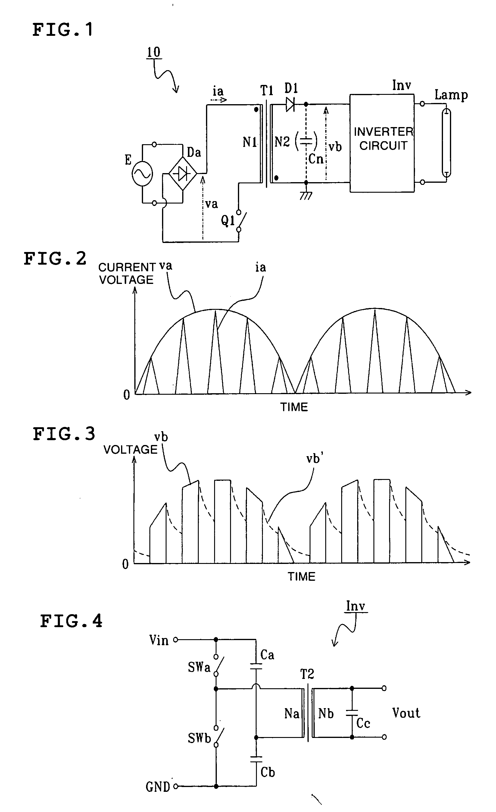
[0028] A circuit diagram of a preferred embodiment of a switching power supply unit of the present invention is shown in FIG. 1. In FIG. 1, a switching power supply unit 10 according to a preferred embodiment of the present invention includes a full-wave rectifying circuit Da, a transformer T1 having a primary winding N1 and a secondary winding N2, a switching element Q1, a diode D1, and an inverter circuit Inv.

[0029] The input side of the full-wave rectifying circuit Da is connected to a commercial AC power supply E. The primary winding N1 of the transformer T1 and the switching element Q1 are connected in series on the output side of the full-wave rectifying circuit Da. No smoothing capacitor of large capacitance is provided on the output side of the full-wave rectifying circuit Da. The full-wave rectifying circuit Da is a primary rectifying circuit.

[0030] One end of the secondary winding N2 of the transformer T1 is connected to the anode of the diode D1 and the other end is con...


PUM


Abstract

A switching power supply unit includes a primary-side rectifying circuit that is connected to a commercial power supply and is arranged to output a primary-side nonsmoothed DC voltage, a transformer having a primary winding and a secondary winding, a switching element connected in series with the primary winding to the output of the primary-side rectifying circuit and arranged to switch the primary-side nonsmoothed DC voltage, a secondary-side rectifying circuit connected to the secondary winding and arranged to output a secondary-side nonsmoothed DC voltage, and an inverter circuit connected to the output of the secondary-side rectifying circuit, and the output is supplied to a gas discharge lamp.

Description

BACKGROUND OF THE INVENTION [0001] 1. Field of the Invention [0002] The present invention relates to a switching power supply unit and more particularly, to a switching power supply unit for power-factor improvement. [0003] 2. Description of the Related Art [0004] Regarding an input voltage in general switching power supply units having a DC output and switching power supply units (inverters) having an AC output, it is common to use a DC voltage with a low level of ripples obtained by rectifying a commercial AC power supply voltage using a rectifier diode and by smoothing it using a large-capacitance smoothing capacitor. This method is known as the capacitor input type. In the capacitor input type, since a large-capacitance smoothing capacitor is provided, when a temporary service interruption occurs on the commercial AC power supply side, if the interruption is for a short time, there is a merit in that the reduction in output voltage can be prevented. [0005] However, in general re...

Claims


Application Information

Patent Timeline
IPC IPC(8): H02M3/335H02M1/42
CPCH02M1/4258H02M2001/007Y02B70/126H02M1/007Y02B70/10H02M1/36H02M3/28
Inventor TAKEMURA, HIROSHINISHIDA, AKIO
Owner MURATA MFG CO LTD
Why Eureka
Try Eureka