
Vehicle Lighting Device

Inactive Publication Date: 2007-04-26
KOITO MFG CO LTD
View PDF13 Cites 26 Cited by
  • Summary
  • Abstract
  • Description
  • Claims
  • Application Information

AI Technical Summary

Benefits of technology

[0008] One or more embodiments of the present invention provide a vehicle lighting device capable of preventing the driver of another vehicle from being dazzled and enhancing the driver's visibility thus obtaining a light distribution characteristic effective for safe traveling.
[0010] In accordance with one or more embodiments of the invention, by independently changing and controlling the light distribution characteristic of only one of the lamps, it is possible to arbitrarily change the overlapping form of the illumination light of the one lamp and that of the other lamp thereby providing a vehicle lighting device having a variety of light distribution characteristics. This obtains, for example, a light distribution characteristic where the luminosity of the direct front area of the own vehicle in a rainy weather is somewhat reduced, thereby preventing the driver of an oncoming vehicle from being dazzled by the light reflected on the road surface in the direct front area. At the same time, this avoids the direct front area being in a substantially entirely dark state and improves the visibility of the direct front area of the own vehicle and prevents a linear-stripe-shaped dark and light caused by the possible substantially entirely dark state, thus relieving the driver from discomfort. It is also possible to obtain a light distribution characteristic that illuminates the areas ahead of the own vehicle with high luminosity without dazzling the driver of the oncoming vehicle in high-speed traveling.

Problems solved by technology

In the techniques disclosed in JP-A-2004-327187 and JP-A-2005-011608, the right and left lamps have the same light distribution characteristic and the illumination light beams of the same light distribution characteristic overlap each other to illuminate the front area of the vehicle, so that the difference in luminosity between an area where the illumination light beams overlap each other and an area where the beams do not overlap each other is extremely eminent, which brings discomfort for a driver and degrades visibility.
This results in linear-stripe-shaped light and dark across the illuminated area, which brings discomfort for the driver as well as an obstacle in terms of safety traveling.
However, this approach is limited to a combination of fixed light distribution characteristics thus narrowing the freedom of controllable light distribution characteristic.
Thus, it is difficult to obtain a light distribution characteristic that decreases the luminosity just in front of the own vehicle in a rainy weather like in JP-A-2004-327187 and JP-A-2005-011608 prevent the driver of another vehicle from being dazzled by the reflection on the road surface.
This narrows the freedom of controllable light distribution characteristic and presents an obstacle of safe traveling.

Method used


Image

  • Vehicle Lighting Device
  • Vehicle Lighting Device
  • Vehicle Lighting Device

Examples


first exemplary embodiment

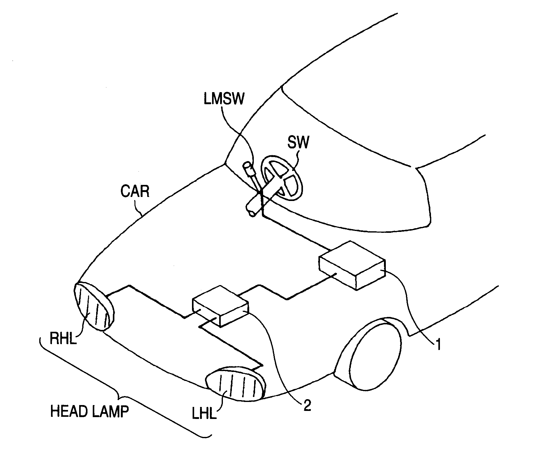
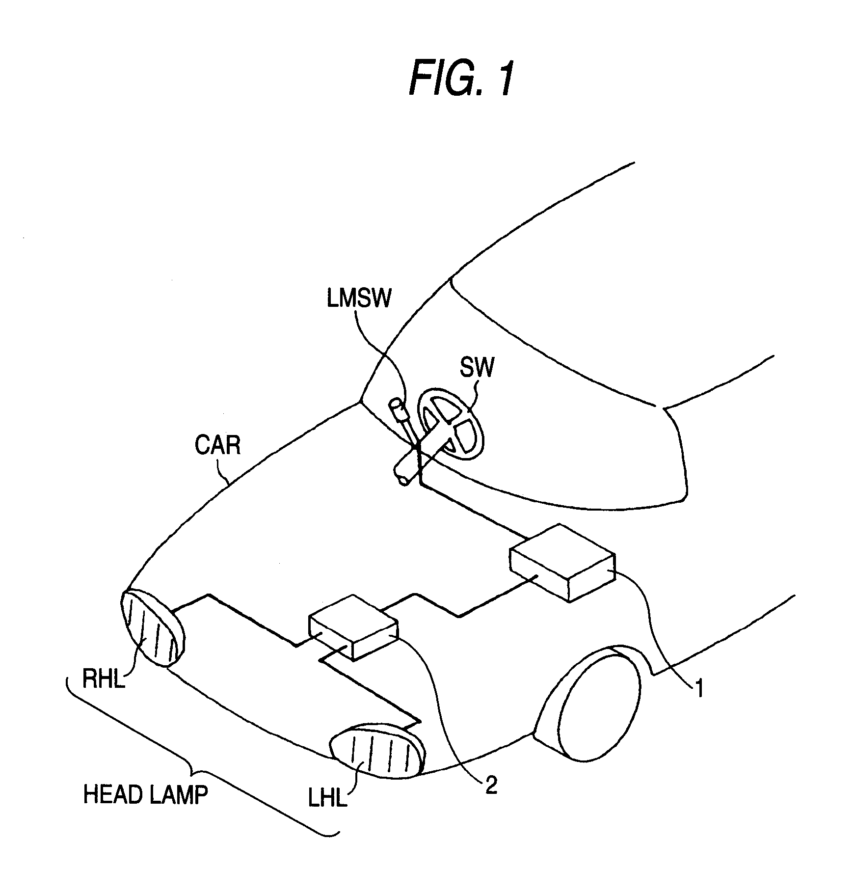
[0031]FIG. 1 is a schematic view of a first exemplary embodiment where a lighting device according to a first exemplary embodiment composed of a pair of headlamps arranged on the right and left sides of a front part of an automobile. When a driver in a driver's seat of the automobile CAR operates a lamp mode selector switch LMSW provided in close proximity to a steering wheel SW to switch between modes as described later, a central processing unit (hereinafter referred to as the CPU) 1 receives a mode signal from the lamp mode selector switch LMSW to control a lamp controller 2 to cause it to independently control the light distribution characteristic, that is, the light distribution pattern shape of each of the left headlamp LHL and the right headlamp RHL. In the first exemplary embodiment, the following lamp modes are available: “traveling mode (high beam mode)”, “passing mode (low beam mode)”, and “rainy weather traveling mode (wet road mode)”.

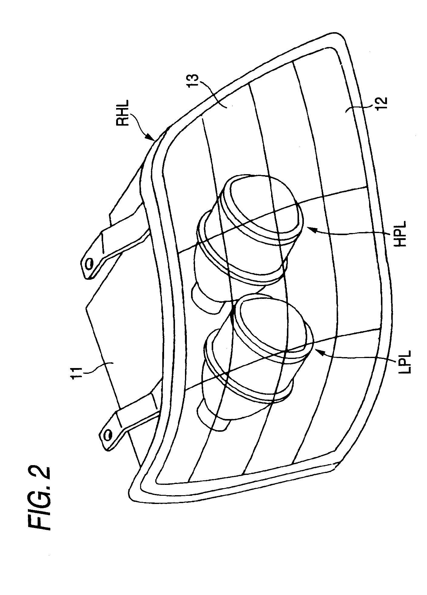
[0032]FIG. 2 is a schematic view of...

second exemplary embodiment

[0041] In a lighting device of a second exemplary embodiment, the driver can switch between the “traveling mode”, the “passing mode” and a “middle beam mode”. The “middle beam mode” is a mode callable of illuminating far front area of the own vehicle traveling at a high speed while preventing dazzling of the driver of an oncoming vehicle. FIG. 7 is a schematic view of a right headlamp RHL according to the second exemplary embodiment as an example of the left and right headlamps LHL, RHL of an automobile configured similarly to FIG. 1. A plurality of high beam light source units HLUs and low beam light source units LLUs are arranged in a lamp chamber 13 composed of a lamp body 11 and a transparent cover 12 mounted at the front opening of the lamp body 11. Each light source unit HLU, LLU includes an optical semiconductor device, an LED (light-emitting diode) in this example, as a light source. Each light source unit illuminates light in a predetermined light distribution characteristi...


PUM


Abstract

A vehicle lighting device is provided with a pair of lamps arranged on right and left sides of a front part of a vehicle. Illumination light beams emitted from the pair of lamps are overlapped with each other to illuminate a front area of the vehicle. A light distribution characteristic of only one of the lamps is independently changed and controlled. For example, a light distribution characteristic where the luminosity of a direct front area of an own vehicle is somewhat reduced may be obtained by changing the light distribution pattern of one lamp from that of the other lamp. This prevents the driver of an oncoming vehicle from being dazzled by the light reflected on a road surface in the direct front area. At the same time, this avoids the direct front area being in a substantially entirely dark state and improves the visibility of the direct front area.

Description

[0001] This application claims foreign priority from Japanese Patent Application No. 2005-295224, filed on Oct. 7, 2005, the entire contents of which are hereby incorporated by reference. BACKGROUND OF THE INVENTION [0002] 1. Field of the Invention [0003] The present invention relates to a vehicle lighting device of a vehicle such as an automobile, and in particular to a vehicle lighting device capable of appropriately controlling a light distribution characteristic of a headlamp. [0004] 2. Related Art [0005] In order to secure the safe traveling of an automobile, it is a common practice to appropriately change and control a light distribution characteristic of a headlamp depending on a traveling situation of an automobile. The term “light distribution characteristic” refers to a pattern shape of a light intensity distribution of an area illuminated by the headlamp. Thus, the same light intensity distribution pattern shape having a different illumination direction has the same light...

Claims


Application Information

Patent Timeline
IPC IPC(8): F21V1/00F21W107/00F21Y101/00
CPCB60Q1/1415B60Q2300/056B60Q2300/312F21S48/1773F21S41/686
Inventor FUKAWA, KIYOTAKA
Owner KOITO MFG CO LTD
Learn More