
Universal fixed-pixel-size ISP scheme

a fixed-pixel-size, isp-based technology, applied in the direction of instruments, character and pattern recognition, electrical equipment, etc., can solve the problems of line buffers, limited image maximum size, higher power consumption and manufacturing costs, etc., to reduce the size of real estate, reduce cost, and reduce power consumption

Inactive Publication Date: 2007-04-26
MOBILIC TECH CAYMAN CORP
View PDF20 Cites 14 Cited by
  • Summary
  • Abstract
  • Description
  • Claims
  • Application Information

AI Technical Summary

Benefits of technology

"The present invention provides a scheme and method for an Image Signal Processing unit (ISP) with a fixed-size line buffer, regardless of how much larger the size of the image is. The ISP can perform various functions such as color interpolation, color correction, gamma correction, shapeness control, brightness control, contrast control, color effects, color-space conversion, resampling (which includes zooming and scaling), image filtering, and image cropping, using the fixed-size line buffer of the invention. The invention also has low power consumption, reduces cost by reducing the size of the real estate required, and accommodates future increases in the image size of the target sensors or sources. The invention uses a fixed-size line buffer to process image data, which is then stored in segments in a buffer storage. The result is a new and seamless image that is stitched together again using a CPU, DMA, or any other suitable processing unit from the JPEG compressed code by parsing the Restart Marker."

Problems solved by technology

The larger the image is, the bigger the line buffers are and the higher the power consumption and manufacturing cost is.
In addition in an ISP of the related art, the maximum image size is limited by the line buffers.
These disadvantages severely restrict the desire to offer larger image sizes.
It should be noted that the above-cited example of the related art does not address the use of fixed-size line buffer for large image sizes of target sensors whereby such fixed-size line buffers are small and have a universal use because there is virtually no maximum limit in the image size that could be processed by such a fixed-size line buffer.

Method used


Image

  • Universal fixed-pixel-size ISP scheme
  • Universal fixed-pixel-size ISP scheme
  • Universal fixed-pixel-size ISP scheme

Examples


Embodiment Construction

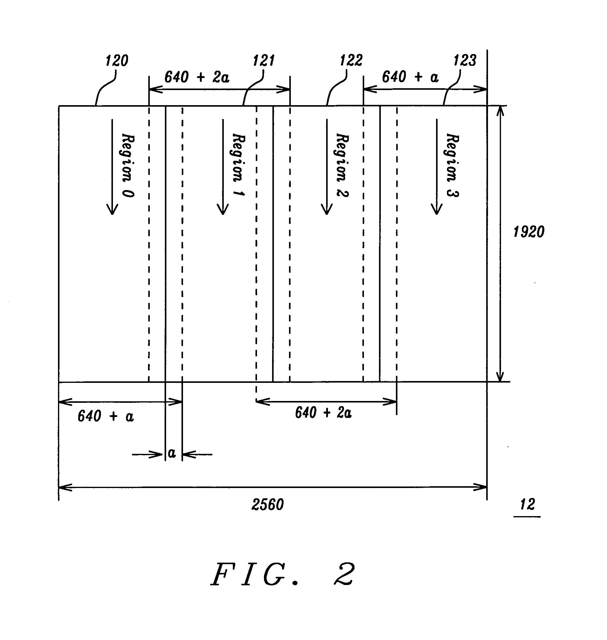
[0020] The present invention describes a scheme and a method by which a fixed-size line buffer of an Image Signal Processing unit (ISP) need only be a fraction of the image size of the target sensors or other input devices or sources. This is done by partitioning the image into multiple segments or regions and subsequently loading one scan line of each segment or region into the fixed-size line buffer (the number of fixed-size line buffers may be more than one). In particular, the width of the fixed-size line buffer is smaller than the width of the image buffer.

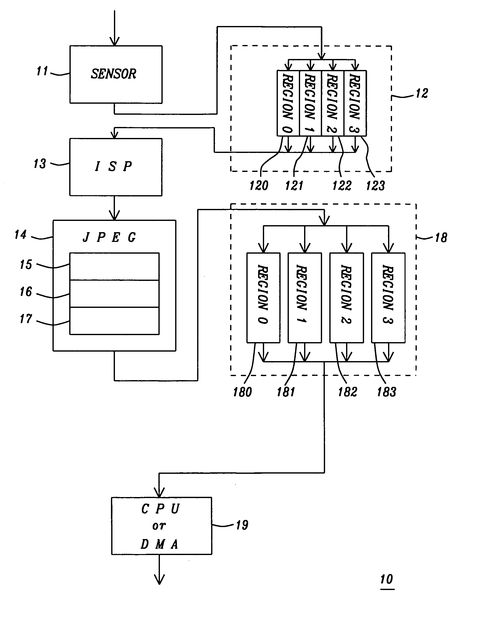
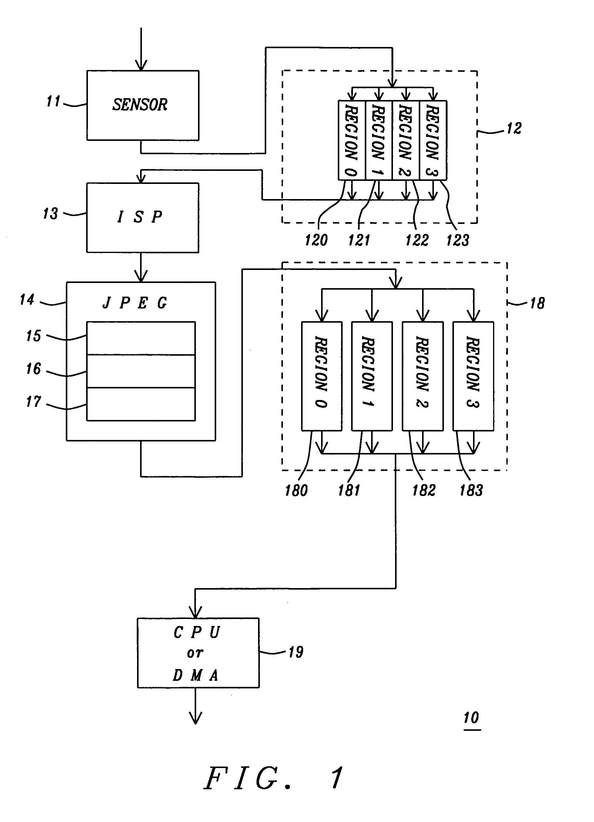
[0021]FIG. 1 illustrates in block format the Universal Fixed-Pixel-Size ISP scheme 10 of a first preferred embodiment of the present invention. Block 11 is the sensor which feeds the raw Image Buffer 12, which is a storage means such as a DRAM or an SDRAM or any other suitable storage device. Image Buffer 12 is shown by way of example to have four regions: Region 0 (120), Region 1 (121), Region 2 (122), and Region 3 (123). T...


PUM


Abstract

An Image Signal Processing unit (ISP) has at least one fixed-size line buffer which is smaller than the width of the image buffer. To handle the image data, the image buffer is divided into regions which are sequentially loaded into the at least one fixed-size line buffer of the ISP for processing. Since functions of the ISP operate with neighboring pixels of the target pixel, margins of the regions need to be transmitted as well. After processing by the ISP, the data is encoded which includes a DCT, Quantization, and VLC. The result is then stored in segments in a buffer storage. VLC also inserts a Restart Marker which is used as a pointer to stitch together all the segments thus producing a new and seamless image.

Description

BACKGROUND OF THE INVENTION [0001] 1. Field of the Invention [0002] The invention relates to a scheme of using a fixed-size Image Signal Processing unit in digital camera applications, and more particularly to a scheme where the line buffer size is a fraction of the image size of the target sensors, other input devices or sources. [0003] 2. Description of the Related Art [0004] Traditionally an ISP (Image Signal Processing unit) needs many line buffers in order to perform the functions like Color Interpolation, zooming / Scaling, etc. The size of the line buffers (and their associated control logic) is typically tailored to the maximum image size of the target sensors. The larger the image is, the bigger the line buffers are and the higher the power consumption and manufacturing cost is. In addition in an ISP of the related art, the maximum image size is limited by the line buffers. These disadvantages severely restrict the desire to offer larger image sizes. To cope with the trend of...

Claims


Application Information

Patent Timeline
Patent Type & Authority Applications(United States)
IPC IPC(8): H04N1/413
CPCH04N1/40
Inventor REN, JAU-WEN
Owner MOBILIC TECH CAYMAN CORP
Learn More