
Capacitor strap

a capacitor and strap technology, applied in the field of security tags, can solve the problems of increasing the complexity of the manufacturing machinery required for production, increasing the processing time and cost per unit, and reducing the service life of the capacitor,

Inactive Publication Date: 2007-04-26
CHECKPOINT SYST INC
View PDF28 Cites 43 Cited by
  • Summary
  • Abstract
  • Description
  • Claims
  • Application Information

AI Technical Summary

Benefits of technology

[0009] A strap component for electrically bridging at least two respective portions of an antenna or coil component of an EAS or RFID tag or inlay. The strap component is a thin, generally planar member comprising a first electrically conductive planar element, a second planar electrically conductive element and a planar dielectric layer disposed between at least portions of the first and second electrically conductive planar elements...

Problems solved by technology

However, such products utilize, and indeed require, substrates which use patterned sides of conductive material on both face surfaces of the substrate for proper operation.
For example, since special patterning and etching techniques must be utilized on both sides of the available tags to produce the proper circuit, per unit processing time and costs are increased.
Furthermore, the complexity of the manufacturing machinery required for production is also increased.
As may be appreciated, two sided photo-etching is generally time consuming and requires precise alignment of the patterns on both sides.
Additional material is also necessary to pattern both sides, thus increasing the per unit material costs.

Method used


Image

  • Capacitor strap
  • Capacitor strap
  • Capacitor strap

Examples


Embodiment Construction

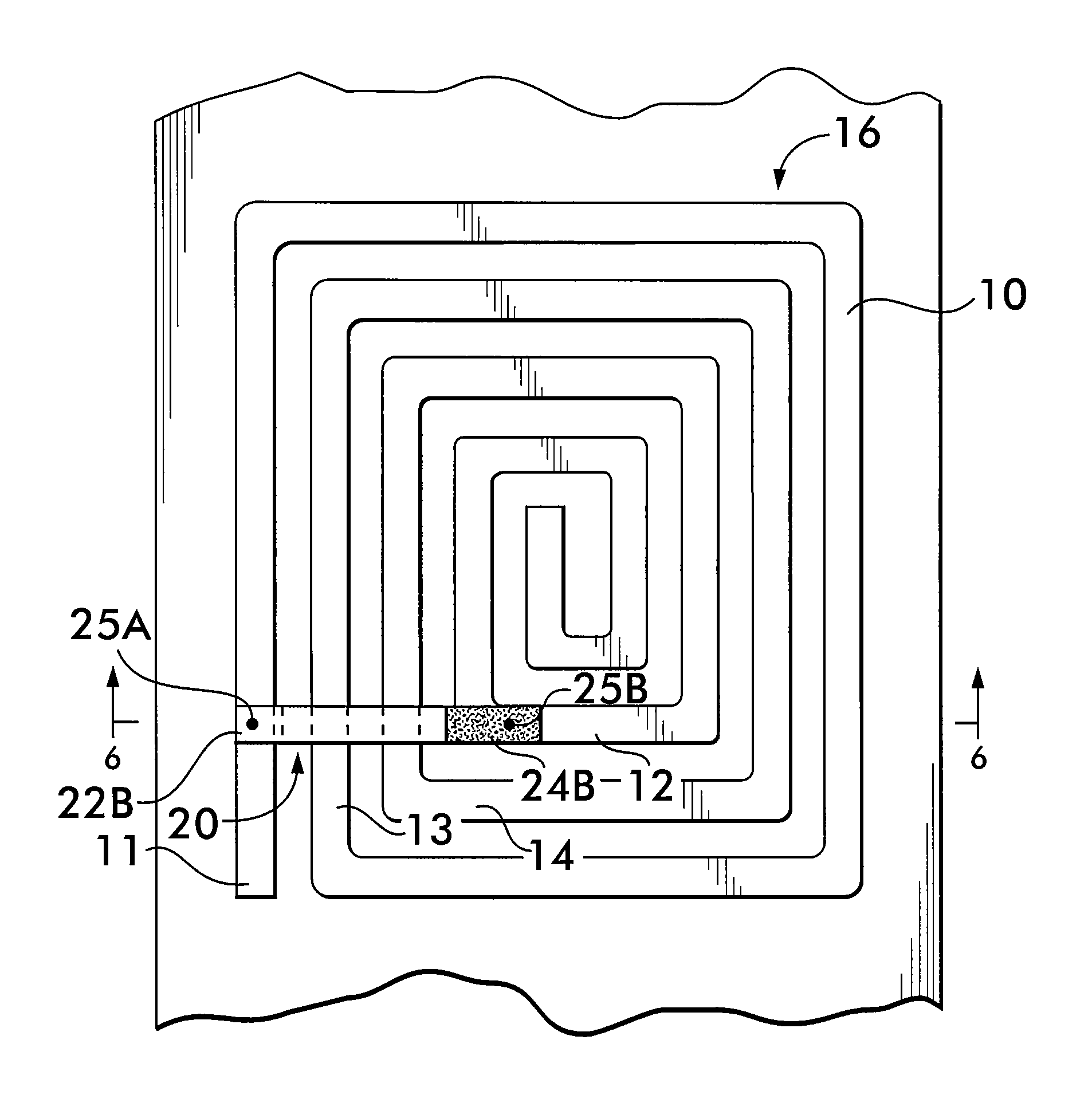
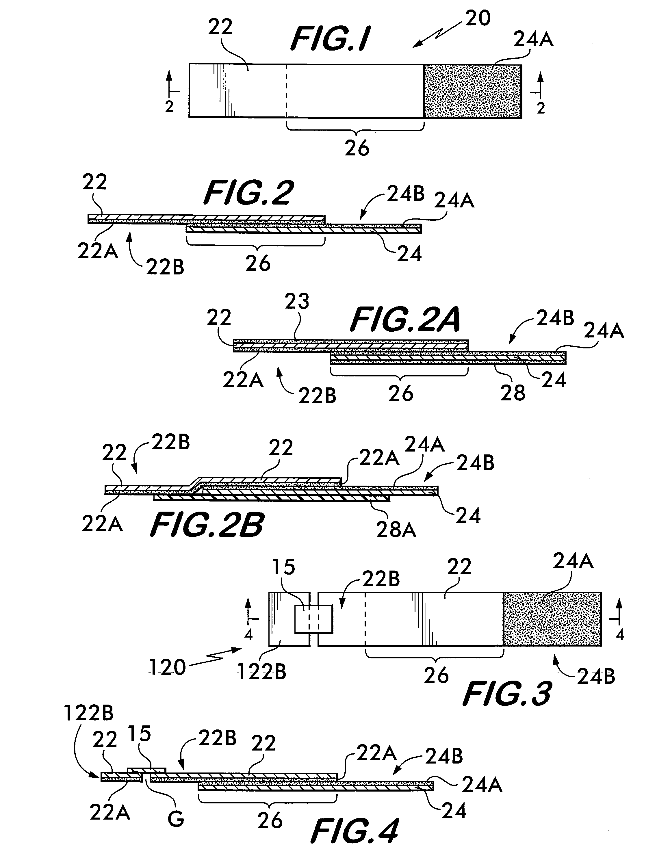
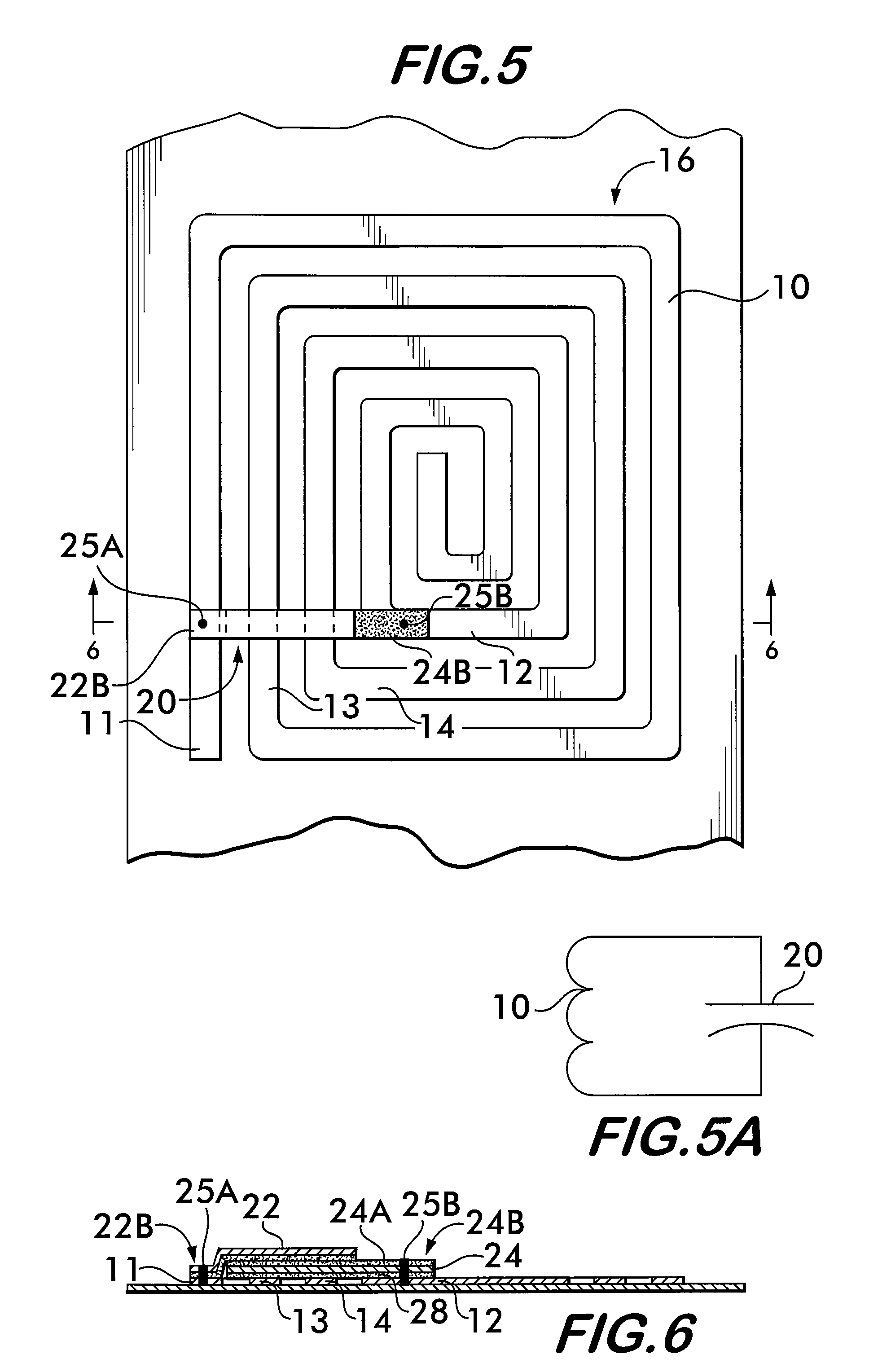
[0041]FIG. 1 depicts an enlarged plan view of a capacitor strap 20 of the present invention. As can be seen most clearly in FIG. 2, the capacitor strap 20 is a thin film capacitor, and may be flexible, that comprises a first electrically conductive planar element 22 having an associated dielectric layer 22A and a second electrically conductive planar element 24 having an associated dielectric layer 24A and wherein portions of the elements 22 and 24 overlap 26, thereby forming a capacitor. As is known to those skilled in the art, the amount of overlap 26 determines the capacitance.

[0042] Although there are many ways of forming the capacitor strap 20, the preferred method is to provide a pair of rolls, each containing a metal foil (e.g., aluminum) that is heat fused to a dielectric material (e.g., a heat seal dielectric material such as polyester or polyethylene which readily bonds to aluminum; however, other dielectric materials, such as a styrene-acylate polymer or a vinyl acetate ...


PUM


Abstract

A capacitor strap that is applied to a security tag coil or antenna to form and properly tune an EAS or an RFID security tag. The capacitor strap is a thin film capacitor formed of two metal foils in between which is a dielectric material having ends that are electrically coupled to different points of a security tag coil or antenna. The capacitor strap may include an RFID integrated circuit, either in series or in parallel with the capacitor, which is then applied to security tag coil at a particular location to tune the tag to a predetermined frequency.

Description

CROSS-REFERENCE TO RELATED APPLICATIONS [0001] This utility application claims the benefit under 35 U.S.C. §119(e) of Provisional Application Ser. No. 60 / 730,053 filed on Oct. 25, 2005 entitled CAPACITOR STRAP and whose entire disclosure is incorporated by reference herein.BACKGROUND OF THE INVENTION [0002] 1. Field of Invention [0003] The current invention relates to security tags and more particularly, discloses a capacitor strap that can be applied to an EAS or RFID coil or antenna to complete the EAS or RFID tag. [0004] 2. Description of Related Art [0005] Electronic article surveillance (EAS) security tags, typically comprise a resonant circuit that utilize at least one coil and at least one capacitor that operate to resonate when exposed to a predetermined electromagnetic field (e.g., 8.2 MHz) to which the EAS tag is exposed. By way of example only, the coil and the capacitor are etched on a substrate whereby a multi-turn conductive trace (thereby forming the coil) terminates ...

Claims


Application Information

Patent Timeline
IPC IPC(8): G08B13/14
CPCG06K19/07718G06K19/07749G06K19/07752
Inventor COTE, ANDRESOLER BONNIN, LUIS FRANCISCO
Owner CHECKPOINT SYST INC
Learn More