
Apparatus for accurate and efficient quality and reliability evaluation of micro electromechanical systems

a micro-electromechanical system, accurate and efficient technology, applied in the direction of electrical apparatus, electrostrictive/piezoelectric relay, electromagnetic relay, etc., can solve the problems of large sample sizes for accurate statistical determination, difficult application of reliability and qualification methods for process enhancements and lifetime predictions, and impracticality of testing large sample sizes. , to achieve the effect of accurate measuremen

Inactive Publication Date: 2007-04-26
GLOBALFOUNDRIES INC
View PDF4 Cites 33 Cited by
  • Summary
  • Abstract
  • Description
  • Claims
  • Application Information

AI Technical Summary

Benefits of technology

[0009] It is another object of the present invention to provide an apparatus and method for testing MEMS relay devices that accommodates the testing of a large number of devices and provides accurate measurements for certain device parameters.
[0010] A further object of the invention is to provide an apparatus for testing multiple MEMS switches on a semiconductor circuit chip without requiring a large number of probe pads.

Problems solved by technology

While the development of these MEMS switches are in the early development stage, their performance must be empirically characterized; however, reliability and qualification methods for process enhancements and lifetime predictions are difficult to apply and require large sample sizes for accurate statistical determination.
Generally, the layout and fabrication of the MEMS devices makes the testing of large sample sizes impractical.
These options quickly become expensive and impractical.

Method used


Image

  • Apparatus for accurate and efficient quality and reliability evaluation of micro electromechanical systems
  • Apparatus for accurate and efficient quality and reliability evaluation of micro electromechanical systems
  • Apparatus for accurate and efficient quality and reliability evaluation of micro electromechanical systems

Examples


Embodiment Construction

)

[0033] In describing the preferred embodiment of the present invention, reference will be made herein to FIGS. 1-13 of the drawings in which like numerals refer to like features of the invention.

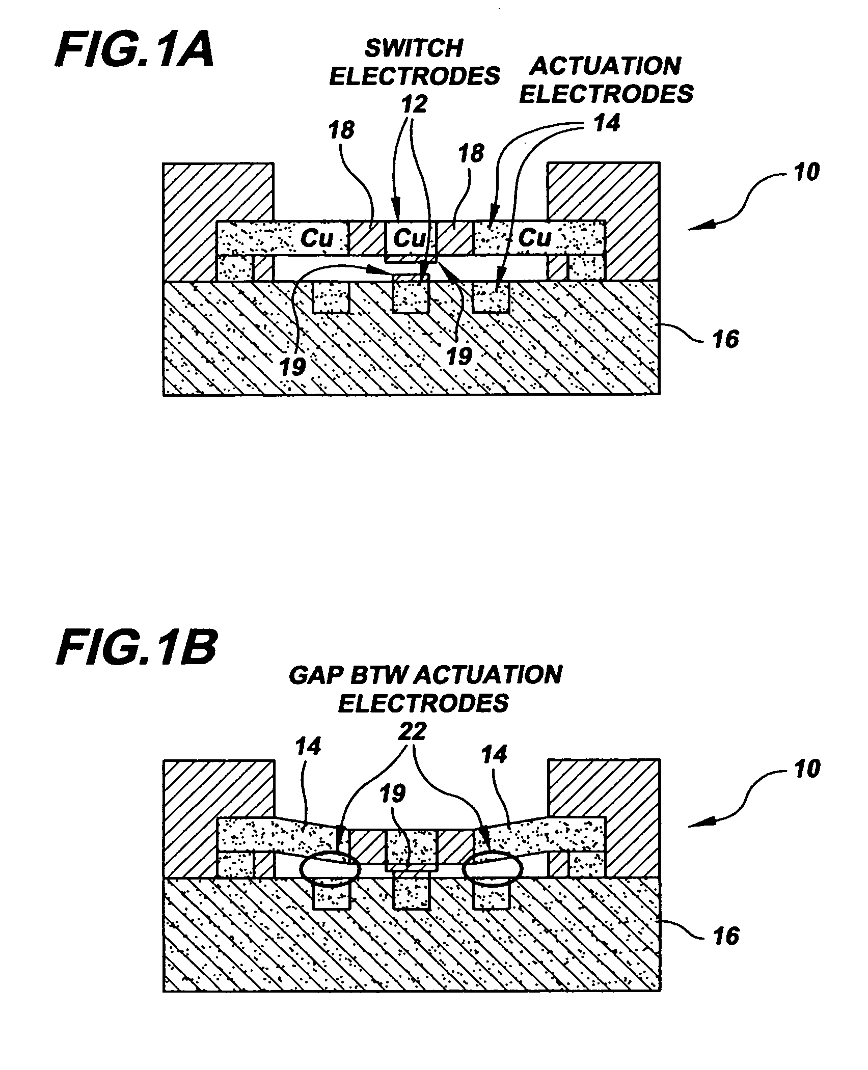
[0034]FIG. 1A depicts a MEMS relay 10 in the OPEN state having switch electrodes 12 and actuation electrodes 14. The MEMS relay 10 is configured on a silicon substrate 16. The switch electrodes are electrically isolated from the actuation electrodes by an inter-dielectric layer (ILD) 18. Contacts 19 are situated on upper and lower faces of the switch electrodes. FIG. 1B depicts the MEMS relay 10 of FIG. 1A with the relay show in a CLOSED or ACTIVATED state. This occurs when the switch is supplied with an actuation voltage. Contacts 19 are shown in electrical contact, while the actuation electrodes 14 are held close together but remain spaced apart between gaps 22 during the actuation period. By applying an actuation voltage, the switch beam is brought into physical contact with the lower c...


PUM


Abstract

The present invention provides multiple test structures for performing reliability and qualification tests on MEMS switch devices. A Test structure for contact and gap characteristic measurements is employed having a serpentine layout simulates rows of upper and lower actuation electrodes. A cascaded switch chain test is used to monitor process defects with large sample sizes. A ring oscillator is used to measure switch speed and switch lifetime. A resistor ladder test structure is configured having each resistor in series with a switch to be tested, and having each switch-resistor pair electrically connected in parallel. Serial / parallel test structures are proposed with MEMS switches working in tandem with switches of established technology. A shift register is used to monitor the open and close state of the MEMS switches. Pull-in voltage, drop-out voltage, activation leakage current, and switch lifetime measurements are performed using the shift register.

Description

BACKGROUND OF THE INVENTION [0001] 1. Field of the Invention [0002] The invention relates to micro electromechanical systems, particularly to micro electromechanical switches and structures for testing the same. More specifically, the invention relates to test structures and test methods to acquire reliability and qualification data in order to characterize MEMS switch performance with statistical significance. [0003] 2. Description of Related Art [0004] Micro Electromechanical Systems (MEMS) are being considered for possible switch structures in advanced high performance analog circuitry, in part, because of the improved switching characteristics over FET devices. For example, some MEMS-based RF switches are being developed with superior RF switching characteristics compared to other transistor-based switches, such as GaAs MESFETs, and the like. [0005] While the development of these MEMS switches are in the early development stage, their performance must be empirically characterize...

Claims


Application Information

Patent Timeline
Patent Type & Authority Applications(United States)
IPC IPC(8): H01H51/22
CPCH01H59/0009
Inventor DELIGIANNI, HARIKLIAEDWARDS, ROBERT D.FLEISCHMAN, THOMAS J.GROVES, ROBERT A.MONTROSE, CHARLES J.VOLANT, RICHARD P.WANG, PING-CHUAN
Owner GLOBALFOUNDRIES INC
Learn More