
Helmet with shock detector, helmet attachment device with shock detector & methods

a technology of helmet attachment and detector, which is applied in the direction of instruments, acceleration measurement using interia forces, sport apparatus, etc., can solve the problems of not being able to absorb the energy of another collision, damage to the shock absorbing liner, and being visually undetectabl

Inactive Publication Date: 2007-04-26
BECK GREGORY S
View PDF9 Cites 84 Cited by
  • Summary
  • Abstract
  • Description
  • Claims
  • Application Information

AI Technical Summary

Benefits of technology

[0004] This invention has one or more features as discussed subsequently herein. After reading the following section entitled “DETAILED DESCRIPTION OF SOME EMBODIMENTS OF THIS INVENTION,” one will understand how the features of this invention provide its benefits. These benefits include, but are not limited to: (a) detection of a potentially damaging impact to a helmet not otherwise visually detectable, (b) detection of head injuries experienced by athletes, military personnel, an other wearing a helmet, and (c) a low cost, convenient to mount attachment device adapted to be connected to a conventional helmet not having a shock detector.

Problems solved by technology

Once compressed the foam plastic liner remains compacted, and thereafter is not as capable of absorbing the energy of another collision.
The outer shell usually has sufficient flexibility to return to its normal condition and the damage to the shock absorbing liner is visually undetectable.
In other words, one impact may render the helmet incapable of thereafter adequately protecting the user, but the degradation of the shock absorbing character of the liner is unnoticed.
Although one high-energy impact may render the helmet incapable of adequately protecting the user, several repeated low energy impacts may also render the helmet incapable of adequately protecting the user.
Manufactures of various types of helmets fail to recognize that such repeated low energy impacts degrade the ability of the helmet to protect the user.
Consequently, there is a risk of an athlete in a contact sport such as, for example, lacrosse, hockey, football, skiing, snow boarding, etc., sustaining a serious head injury because the helmet has lost its ability to absorb the energy of even a low level impact due to sustaining a number of low level impacts.
Moreover, soldiers and other military personnel, frequently experience brain injuries from bomb blasts even when wearing a helmet, but are unaware of such injury.

Method used


Image

  • Helmet with shock detector, helmet attachment device with shock detector & methods
  • Helmet with shock detector, helmet attachment device with shock detector & methods
  • Helmet with shock detector, helmet attachment device with shock detector & methods

Examples


Embodiment Construction

,” one will understand how the features of this invention provide its benefits. These benefits include, but are not limited to: (a) detection of a potentially damaging impact to a helmet not otherwise visually detectable, (b) detection of head injuries experienced by athletes, military personnel, an other wearing a helmet, and (c) a low cost, convenient to mount attachment device adapted to be connected to a conventional helmet not having a shock detector.

[0005] Without limiting the scope of this invention as expressed by the claims that follow, some, but not necessarily all, of its features are:

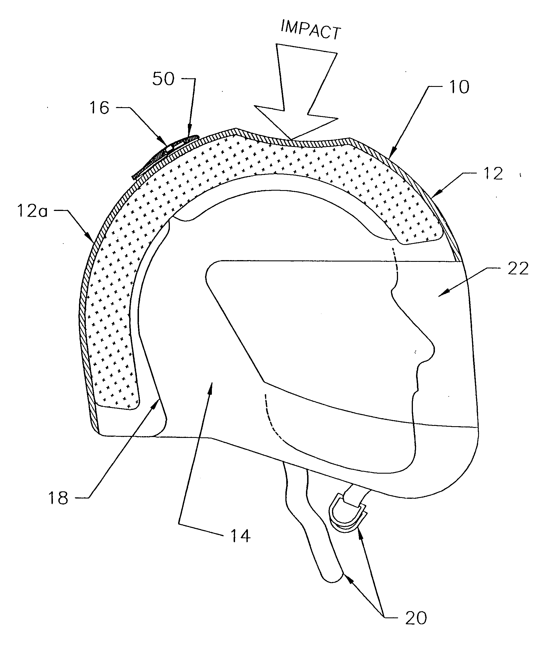
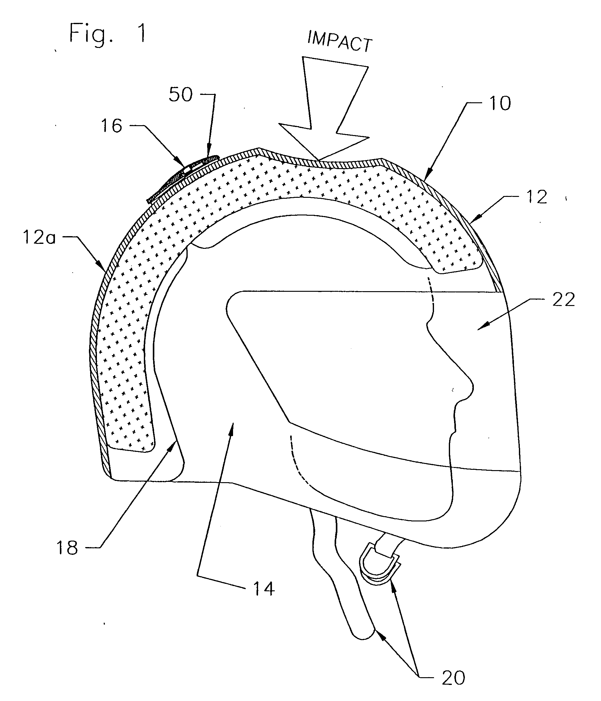
[0006] One, the helmet of this invention includes a head enclosure with an open cavity for the head of a user and a shock detector attached to the head enclosure. The helmet may or may include internal impact absorbing liner, and my be of the type worn by athletes, military personnel or other that are likely to sustain a head injury.

[0007] Two, the head enclosure may comprise a tough, subs...


PUM

PropertyMeasurementUnit
accelerationaaaaaaaaaa
elevationaaaaaaaaaa
flexibleaaaaaaaaaa

Abstract

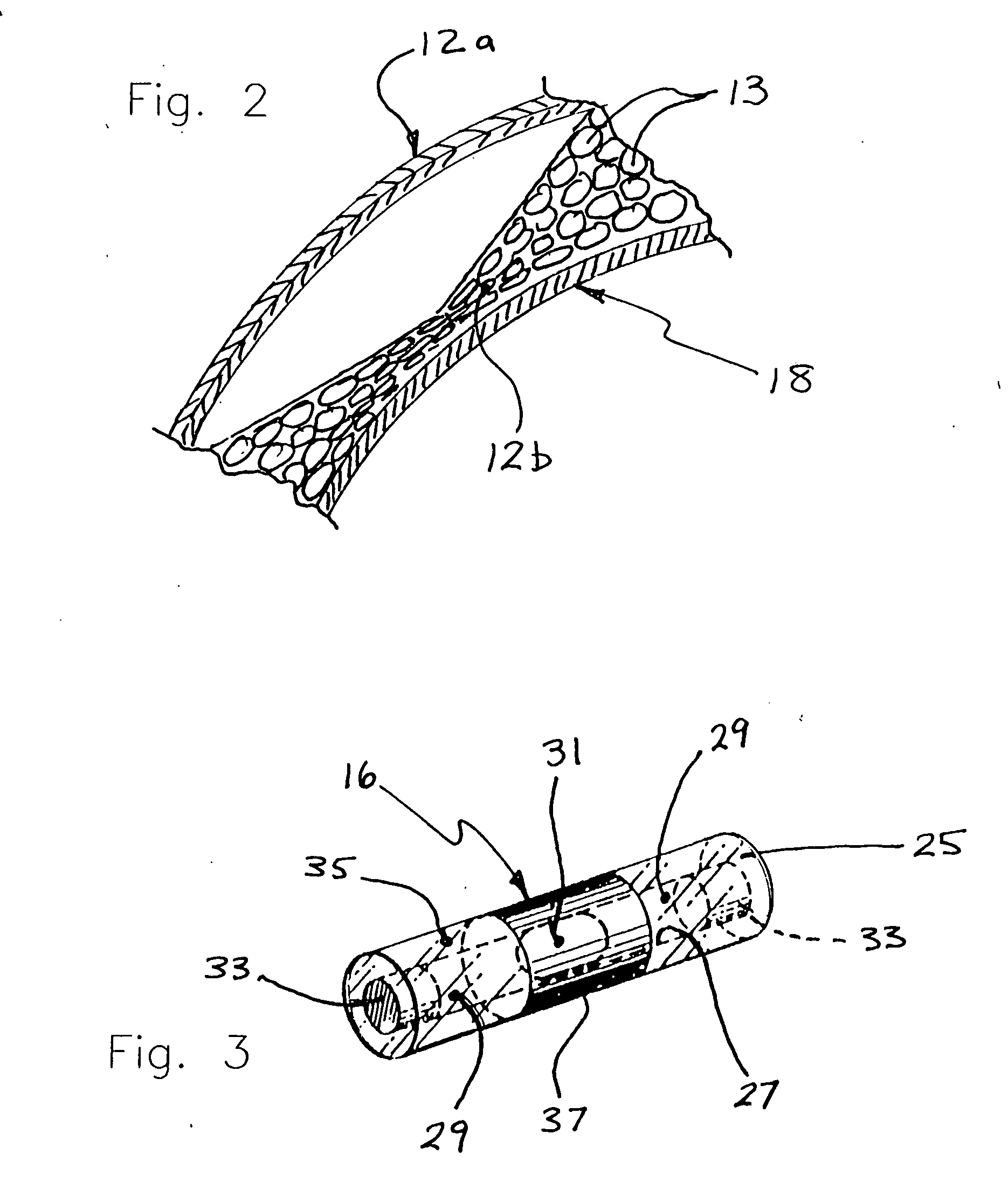
A helmet includes a head enclosure with an open cavity for the head of a user and a shock detector attached to the head enclosure that provides a signal when the head enclosure is subjected an impact exceeding a predetermined level.

Description

RELATED PATENT APPLICATIONS & INCORPORATION BY REFERENCE [0001] This utility application is a continuation-in-part application of the national stage of International Application No. PCT / US2004 / 041798, filed Dec. 9, 2004, which claims the benefit under 35 USC 119(e) of U.S. Provisional Application Ser. No. 60 / 529,453, entitled “Safety Helmet With Shock Detector & Helmet Attachment Device With Shock Detector,” filed Dec. 12, 2003. These related applications, and patents and other documents, hard copy or electronic, cited or referred to in this utility application are incorporated herein by reference and made a part hereof.DEFINITIONS [0002] The words “comprising,”“having,”“containing,” and “including,” and other forms thereof, are intended to be equivalent in meaning and be open ended in that an item or items following any one of these words is not meant to be an exhaustive listing of such item or items, or meant to be limited to only the listed item or items. BACKGROUND OF INVENTION ...

Claims


Application Information

Patent Timeline
Patent Type & Authority Applications(United States)
IPC IPC(8): G01N3/30A42BA42B3/04A63B71/10G01P15/06
CPCA42B3/046A42B3/067A63B71/10G01P15/06
Inventor BECK, GREGORY S.
Owner BECK GREGORY S
Learn More