
Apparatus and method for transmitting/receiving signal in a communication system using low density parity check code

a communication system and low density parity technology, applied in the direction of coding, digital transmission, code conversion, etc., can solve the problems of inability to specify the detailed channel coding/decoding method for supporting a data rate, inability to accurately detect the data rate, and inability to transmit information data. to achieve the effect of reducing the complexity of coding

Active Publication Date: 2007-04-19
SAMSUNG ELECTRONICS CO LTD
View PDF6 Cites 34 Cited by
  • Summary
  • Abstract
  • Description
  • Claims
  • Application Information

AI Technical Summary

Benefits of technology

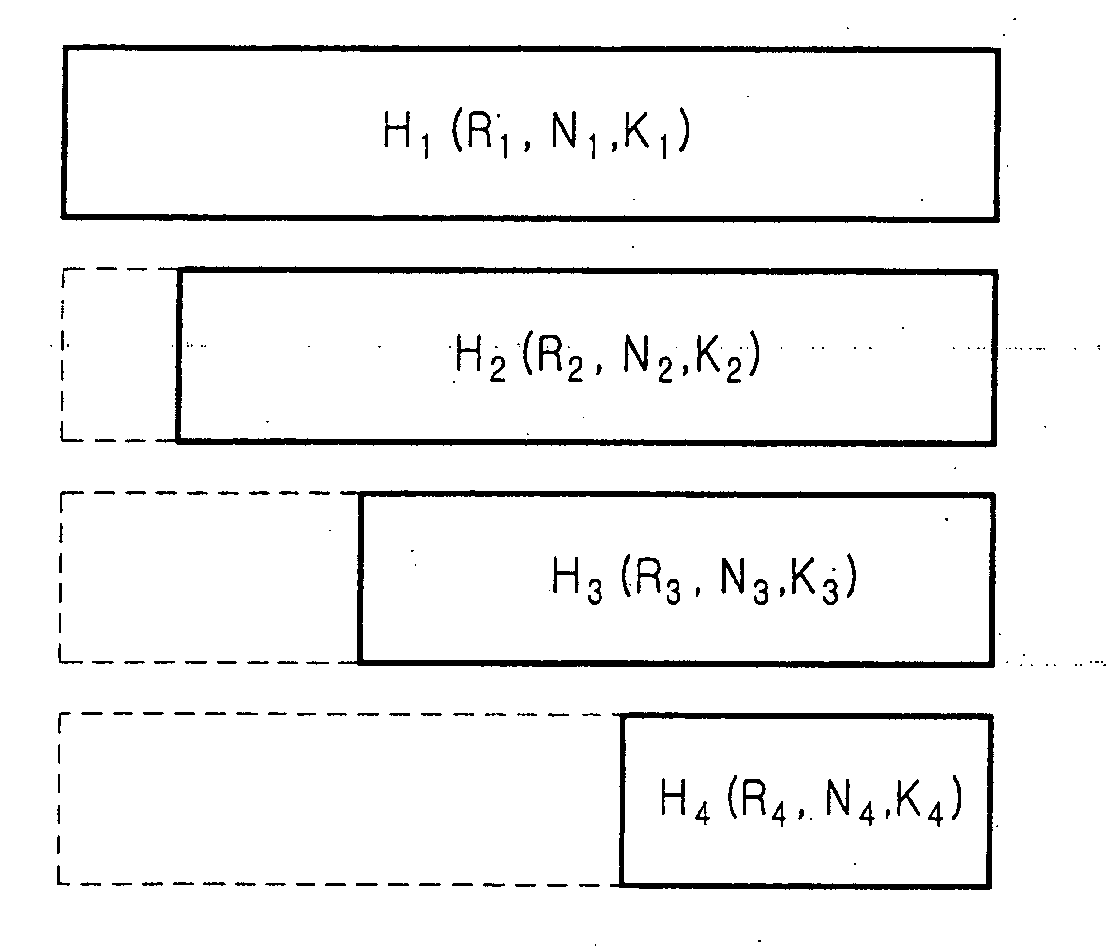
[0045] It is another object of the present invention to provide an apparatus and method for transmitting / receiving signals using a QC-LDPC code supporting a variable coding rate, with minimized coding complexity, in a communication system.

Problems solved by technology

However, due to the characteristics of the mobile communication system, it inevitably incurs error during data transmission due to noises, interference and fading according to channel conditions.
The error causes a loss of information data.
However, Shannon's channel coding theorem has proposed no detailed channel coding / decoding method for supporting a data rate up to the maximum channel capacity limit.
Generally, although a random code having a very large block size shows performance approximating the channel capacity limit of Shannon's channel coding theorem, when a MAP (Maximum A Posteriori) or ML (Maximum Likelihood) decoding method is used, it is impossible to implement the decoding method because of its heavy calculation load.
However, when there are too many short-length cycles in the factor graph, performance degradation is expected.
An increase in the number of short-length cycles causes performance degradation, such as error floor.
Short cycles in the LDPC code are the cause of performance degradation.
As the number of iterations increases, the information returns to the corresponding node more frequently, so that the information cannot be correctly updated, thereby causing deterioration in an error correction capability of the LDPC code.

Method used


Image

  • Apparatus and method for transmitting/receiving signal in a communication system using low density parity check code
  • Apparatus and method for transmitting/receiving signal in a communication system using low density parity check code
  • Apparatus and method for transmitting/receiving signal in a communication system using low density parity check code

Examples


first embodiment

[0102]FIG. 10 is a flowchart illustrating a process of generating a parity check matrix of a rate-compatible QC-LDPC code according to the present invention.

[0103] Referring to FIG. 10, in step 1011, a controller (not shown) of a communication system defines a parameter NB indicating the number of block columns of a parent parity check matrix. In step 1013, the controller substitutes a value NB−1 determined by subtracting 1 from the parameter NB in the parameter NB.

[0104] The reason for substituting the value NB−1 in the parameter NB is to indicate the number of block columns determined by subtracting 1 from the number of block columns of the parent parity check matrix in order to select the block columns to be removed from the parent parity check matrix.

[0105] In step 1015, the controller detects an optimal degree distribution of a parity check matrix that has NB block columns and uses the degree used in the parent parity check matrix. Herein, the optimal degree distribution of t...

second embodiment

[0117]FIG. 11 is a flowchart illustrating a process of generating a parity check matrix of a rate-compatible QC-LDPC code according to the present invention.

[0118] Referring to FIG. 11, in step 1111, a controller (not shown) of a communication system defines a variable NB indicating the maximum number of block columns to be used. In step 1113, the controller defines a variable Ns indicating the minimum number of block columns to be used. In step 1115, the controller detects the optimal degree distribution for when Ns block columns are used. Herein, the optimal degree distribution for when Ns block columns are used is detected using the density evolution scheme. In step 1117, the controller defines a variable i, and substitutes a value Ns+1 determined by adding 1 to the variable Ns in the variable i. Herein, the variable i is used to indicate a parity check matrix that uses i block columns by increasing it one by one.

[0119] In step 1119, the controller detects the optimal degree dis...


PUM


Abstract

An apparatus is provided for transmitting a signal in a communication system using a Low Density Parity Check (LDPC) code. A controller determines a number of ‘0’s to be inserted in information data according to a first coding rate to be applied when generating the information data into an LDPC code, and determines the number of ‘0’s to be removed from the LDPC code. A ‘0’ inserter inserts ‘0s’ in the information data according to control of the controller. An LDPC encoder generates the LDPC code by encoding the ‘0’-inserted signal according to a first parity check matrix. A ‘0’ remover removes the inserted ‘0’s from the LDPC code.

Description

PRIORITY [0001] This application claims the benefit under 35 U.S.C. § 119(a) of an application filed in the Korean Intellectual Property Office on Sep. 27, 2005 and assigned Serial No. 2005-89962, the contents of which are incorporated herein by reference. BACKGROUND OF THE INVENTION [0002] 1. Field of the Invention [0003] The present invention relates generally to an apparatus and method for transmitting / receiving signals in a communication system, and in particular, to an apparatus and method for transmitting / receiving signals in a communication system using Low Density Parity Check (LDPC) codes. [0004] 2. Description of the Related Art [0005] Due to the rapid development of mobile communication systems, there is a need for technology capable of transmitting bulk data approximating the capacity of a wire network even in a wireless network. To meet the increasing demand f6r a high-speed, high-capacity communication system capable of processing and transmitting various data such as ...

Claims


Application Information

Patent Timeline
Patent Type & Authority Applications(United States)
IPC IPC(8): H03M13/00
CPCH03M13/1162H03M13/618H03M13/6306H04L1/14H04L27/00
Inventor LIM, CHI-WOOKYUNG, GYU-BUMPARK, SUNG-EUNKIM, JAE-YOELJEONG, HONG-SILCHOI, SEUNG-HOONPARK, DONG-SEEK
Owner SAMSUNG ELECTRONICS CO LTD
Learn More