
USB circuit device for preventing reverse current from external device

a technology of reverse current and circuit device, which is applied in the direction of dc source parallel operation, instruments, transportation and packaging, etc., can solve problems such as the operation of the p

Inactive Publication Date: 2007-04-19
SAMSUNG ELECTRONICS CO LTD
View PDF4 Cites 33 Cited by
  • Summary
  • Abstract
  • Description
  • Claims
  • Application Information

AI Technical Summary

Benefits of technology

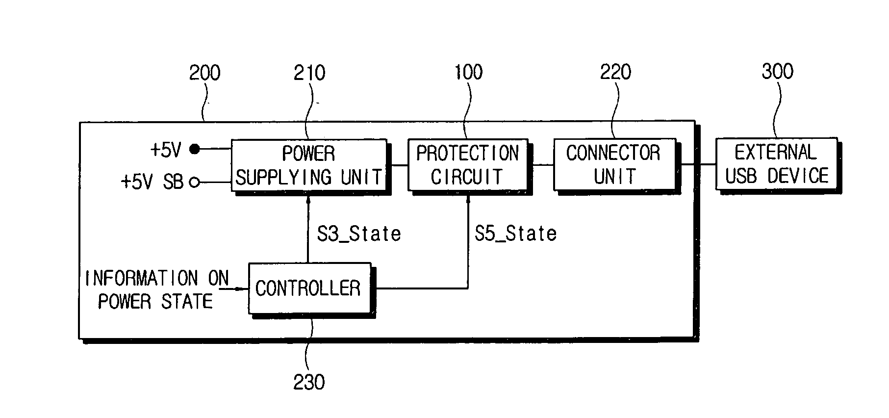
The present invention provides a USB circuit device that prevents reverse current from an external device and protects the circuit from over current while complying with USB specifications. The device includes a connector unit, a power supplying unit, a switching unit, and a controller. The controller controls the switching unit to flow the current induced into the connector unit to the ground if the power provided to the USB device by the power supplying unit is less than a predetermined value. The device also includes at least one internal device receiving the power, and the controller determines that the level of power provided to the USB device is less than the predetermined values if the internal device is in a state of shutting off the power. The power supplying unit outputs a 5V normal power in an S0 state and a 5V standby power in an S3 state. The switching unit includes a FET. The device also includes an over current shutting unit that shuts off the flow of the current induced into the connector unit from the USB device if the current induced into the connector unit from the USB device is more than a predetermined value.

Problems solved by technology

However, when an external device that has its own power source is connected to the PC, if the power of the external device is not shut off when the power of the PC is shut off, a reverse current may be induced from the external device to the PC.
The reverse current influences the operation of the PC and causes problems.

Method used


Image

  • USB circuit device for preventing reverse current from external device
  • USB circuit device for preventing reverse current from external device
  • USB circuit device for preventing reverse current from external device

Examples


Embodiment Construction

[0022] Reference will now be made in detail to embodiments of the present invention, examples of which are illustrated in the accompanying drawings, wherein like reference numerals refer to the like elements throughout. The embodiments are described below in order to explain aspects of the present invention by referring to the figures.

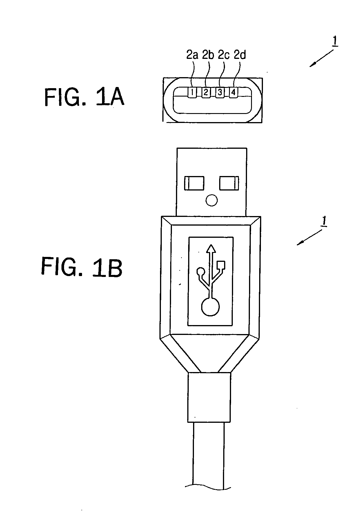
[0023]FIGS. 1A and 1B are a front view and plane view, respectively, illustrating a USB standard connector 1. In the USB interface, the USB standard connector 1 has 4 signal lines as shown in FIG. 1A. The use of each signal line is described in TABLE 1 as follows.

TABLE 1pinsignalnumbernamecontents1VBUSPower signal for supplying power to a device that doesnot have its own power source. In general, power issupplied in the S0 and S3 states, and power is notsupplied in the S5 state.2D−Negative signal among differential signals fortransmitting data.3D+Positive signal among differential signals fortransmitting data.4GNDGround signal.

[0024] Here, S0, S3 an...


PUM


Abstract

A USB circuit device prevents reverse current while complying with USB specifications. A USB circuit device includes a connector unit to which a USB device is connected; a power supplying unit supplying power with the USB device through the connector unit; a switching unit flowing current induced into the connector unit from the USB device, into a ground selectively; and a controller controlling the switching unit to flow the current induced into the connector unit, into the ground if a level of the power provided with the USB device by the power supplying unit is less than a predetermined value. Accordingly, there is provided a USB circuit device for preventing reverse current from an external device and capable of protecting the circuit from over current with satisfaction to a USB specification.

Description

CROSS-REFERENCE TO RELATED APPLICATION [0001] This application claims the benefit of Korean Application No. 2005-97368, filed Oct. 17, 2006 in the Korean Intellectual Property Office, the disclosure of which is incorporated herein by reference. BACKGROUND OF THE INVENTION [0002] 1. Field of the Invention [0003] Aspects of the present invention relate to a USB circuit device, and more particularly, to a USB circuit device that prevents reverse current and that is in compliance with USB specifications. [0004] 2. Description of the Related Art [0005] A universal serial bus (USB) interface is a general-purpose tool that connects a personal computer (PC) with an external device. The USB interface has an additional power signal that provides power to the external device if the device does not have its own power source. However, when an external device that has its own power source is connected to the PC, if the power of the external device is not shut off when the power of the PC is shut ...

Claims


Application Information

Patent Timeline
Patent Type & Authority Applications(United States)
IPC IPC(8): G06F1/00
CPCG06F1/266G06F1/28
Inventor LEE, CHEOL-HO
Owner SAMSUNG ELECTRONICS CO LTD
Learn More