Endoscope And Method For Its Manufacturing

Inactive Publication Date: 2007-04-19
KARL STORZ GMBH & CO KG
View PDF5 Cites 19 Cited by
  • Summary
  • Abstract
  • Description
  • Claims
  • Application Information

AI Technical Summary

Benefits of technology

[0016] A channel which has additionally been filled with an adhesive which is cured is more resistant to bending. This protects the individual optical light guides from breakage.
[0037] This results in plane surfaces at the mouth of the light guide connector on the one side and the distal end of the endoscope shaft on the other side. This allows a light source to be connected to the light guide connector in a manner, that light can be transmitted through the optical light guides uniformly without any loss of stray light. Additionally, the light can be emitted from the distal end of the shaft without stray light.

Problems solved by technology

This results in the shaft not being mechanically very robust, in particular in terms of bending of the shaft.
When the endoscope is being handled, irrespective of whether it is during an intervention or during the subsequent cleaning and autoclaving processes, forces that are applied can result in a bending of the shaft.
A bending of the shaft also bends the inner tube containing the optic system, which can lead to fracture and / or some detachments, for example on the rod lenses of the optics system.
Fracture cracks at the distal and proximal sealing points of the light guides can result in moisture entering into the channel housing the light guides.
This moisture can contain aggressive cleaning liquids, for example peroxide containing liquids, which leads to the destruction of the very fine glass fibers during autoclaving.
Additionally, the loose fibers can break when the shaft is bent remarkably.

Method used


Image

  • Endoscope And Method For Its Manufacturing
  • Endoscope And Method For Its Manufacturing
  • Endoscope And Method For Its Manufacturing

Examples


Embodiment Construction

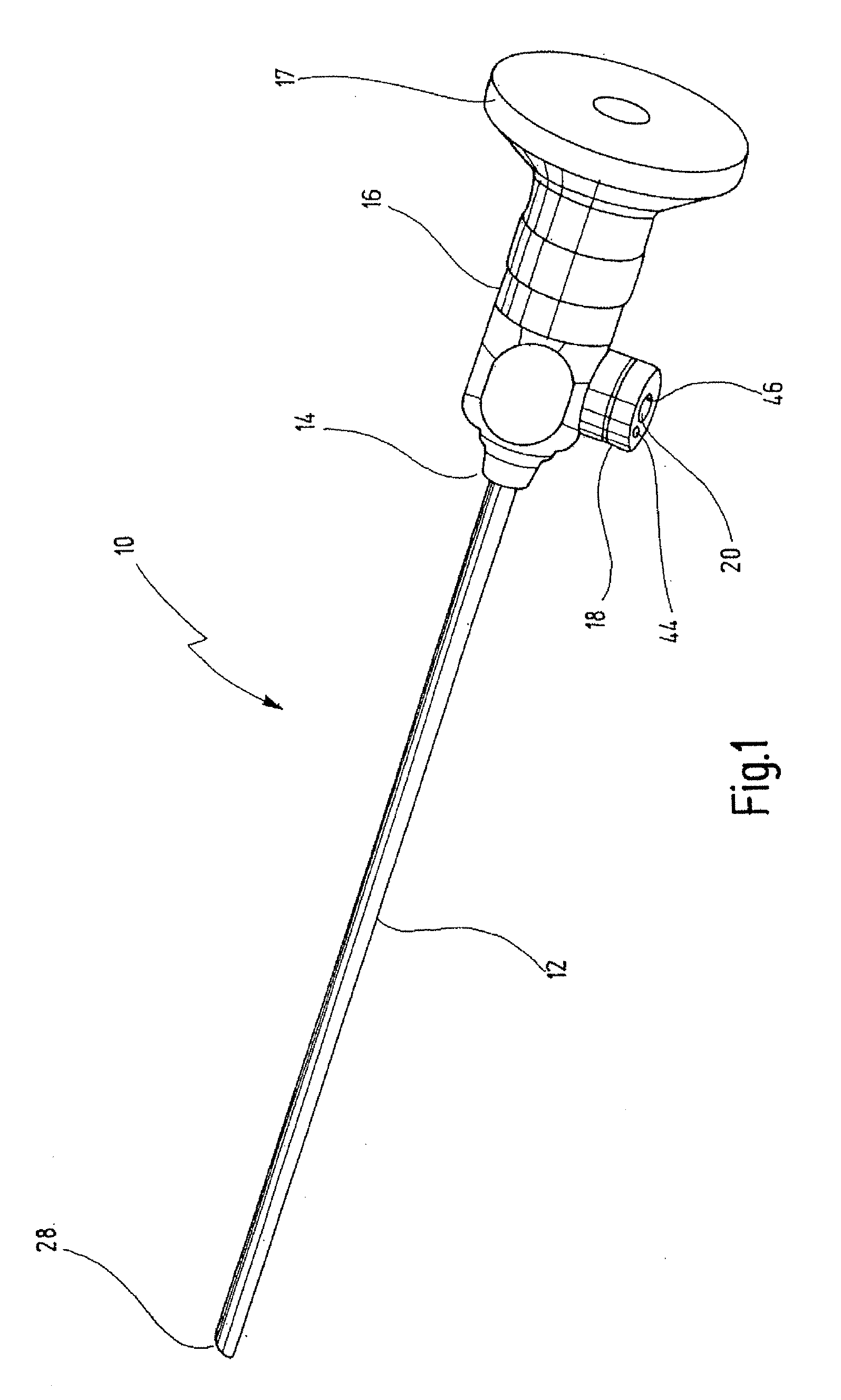
[0044]FIG. 1 shows an endoscope which is designed in its totality with the reference number 10.

[0045] The endoscope 10 has a shaft 12. The shaft 12 is housed at its proximal end 14 in an endoscope head 16. The endoscope head 16 has a light guide connector 18, projecting laterally from the endoscope head 16. A proximal end of the endoscope head 16 shows an ocular 17.

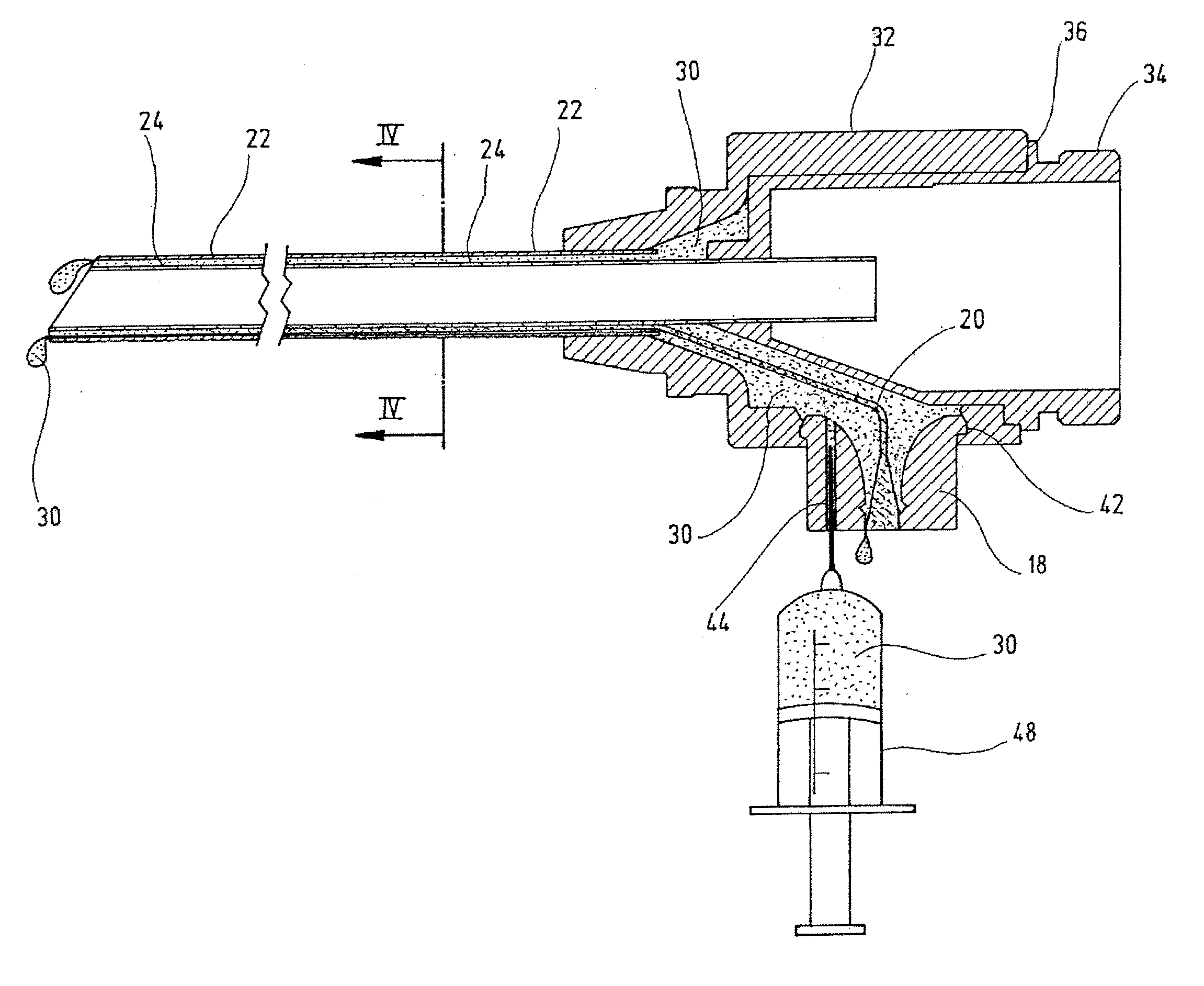
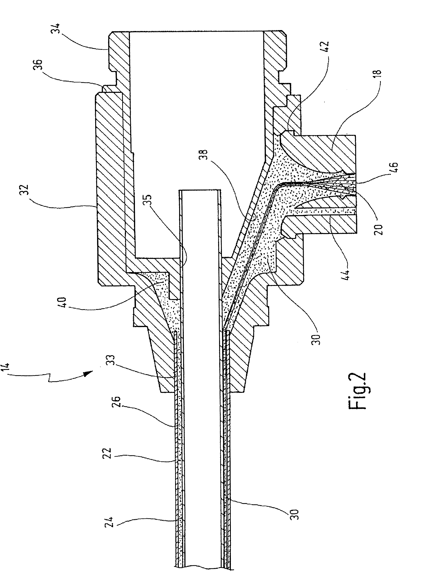
[0046] As can be seen from FIG. 2, the endoscope shaft 12 has a first outer tube 22. A second inner tube 24 having a smaller diameter is inserted into the first tube 22. First tube 22 and second tube 24 are arranged coaxially with respect to another. An annular channel 26 is formed in the endoscope shaft 12 between the inner side of the outer shaft 22 and the outer side of the inner tube 24.

[0047] The endoscope head 16 has a first outer sleeve 32 and a second inner sleeve 34. The outer sleeve 32 has the light connector 18 projecting laterally from the first sleeve 32. The light guide connector 18 has a fitting 42 which...


PUM


Abstract

An endoscope has a shaft which is composed of an outer tube and an inner tube, providing a channel therebetween. The proximal end of the shaft is connected to an endoscope head. The endoscope head is provided with a light guide connector. Light guides extend from said light guide connector to a distal end of said channel in said shaft. Said channel housing said light guides is filled with an adhesive.

Description

BACKGROUND OF THE INVENTION [0001] The invention relates to an endoscope, the shaft of which comprises an outer tube and an inner tube inserted into said outer tube. A channel is disposed between the outer side of said inner tube and the inner side of said inner tube. An endoscope head houses a proximal end of the shaft. A light connector projects, in particular laterally, from said endoscope head. Light guides extend from said light guide connector to a distal end of said channel for guiding light from said light connector to the distal end of the endoscope for illuminating purposes. [0002] Endoscopes of this type are generally known. [0003] Endoscopes are generally used in so-called minimal-invasive surgeries, for example arthroscopy, gastrointestinal examinations and chest cavity examinations, in case of ruptures and during joint and spinal column surgeries. [0004] Within the inner tube, a so-called optic is accommodated, generally a rod lens system or an electronic image recordi...

Claims


Application Information

Patent Timeline
IPC IPC(8): A61B1/06A61B1/00
CPCA61B1/0011A61B1/00165A61B1/0607A61B1/07Y10S600/92
Inventor DAHMEN, JANFURST, FRANK
Owner KARL STORZ GMBH & CO KG
Why Eureka
Try Eureka