
Modular battery system

Inactive Publication Date: 2007-04-19
BATTERY PATENT TRUST
View PDF11 Cites 250 Cited by
  • Summary
  • Abstract
  • Description
  • Claims
  • Application Information

AI Technical Summary

Benefits of technology

[0012] Disclosed herein is a modular battery system having an integrated control unit (ICU) that may be disposed in a system housing. The ICU supports electronics, some of which are used to collect electrical energy produced by the battery modules and monitor the system. Preferably, the ICU includes a battery control module BCM), a fuse, a shunt, a main positive contactor, a main negative contactor, a pre-charge relay and pre-charge resistors. Preferably, each module is in electrical communication with a remote sensing module (RSM), wherein each RSM may communicate with more than one module. The RSM collects performance and status information of each battery module, such as voltage and temperature and relays the information to the BCM. Preferably, the addresses of the RSMs allow the BCM to retrieve the data from all of the RSMs independently.

Problems solved by technology

Therefore, the nickel-metal hydride batteries used in these applications may generate significant heat during operation.
First, ambient heat due to the operation of the vehicle in hot climates.
Third, a tremendous amount of heat is generated during overcharge due to gas recombination.
The cells, with an increased electric capacity and sealed configuration, increase in the amount of heat accumulation, with the result that heat dissipation out of the battery is retarded and the generated heat is accumulated within the battery.
However, neither the '831 patent nor the '008 patent describes a modular battery system with multiple modules secured with rails.
Also, neither the '831 patent nor the '008 patent discloses a module having internal electrical connections between the individual cells within a monoblock.
Second, because Ni-MH has an exceptional energy density (i.e. the energy is stored very compactly) heat dissipation is more difficult than, for example, lead-acid batteries.

Method used


Image

  • Modular battery system
  • Modular battery system
  • Modular battery system

Examples


Embodiment Construction

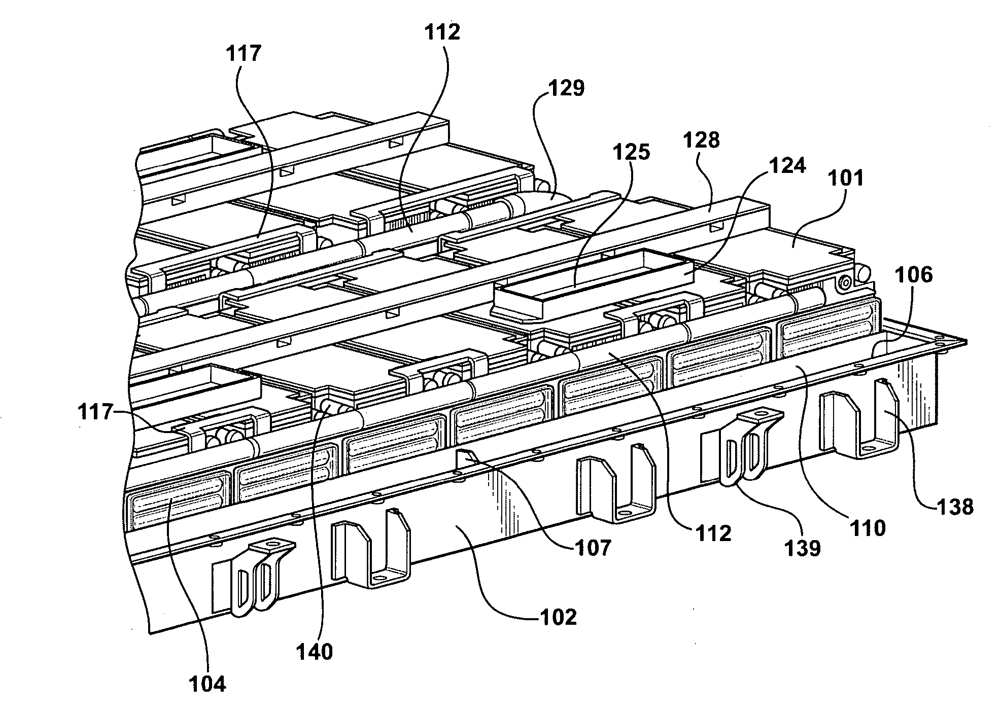
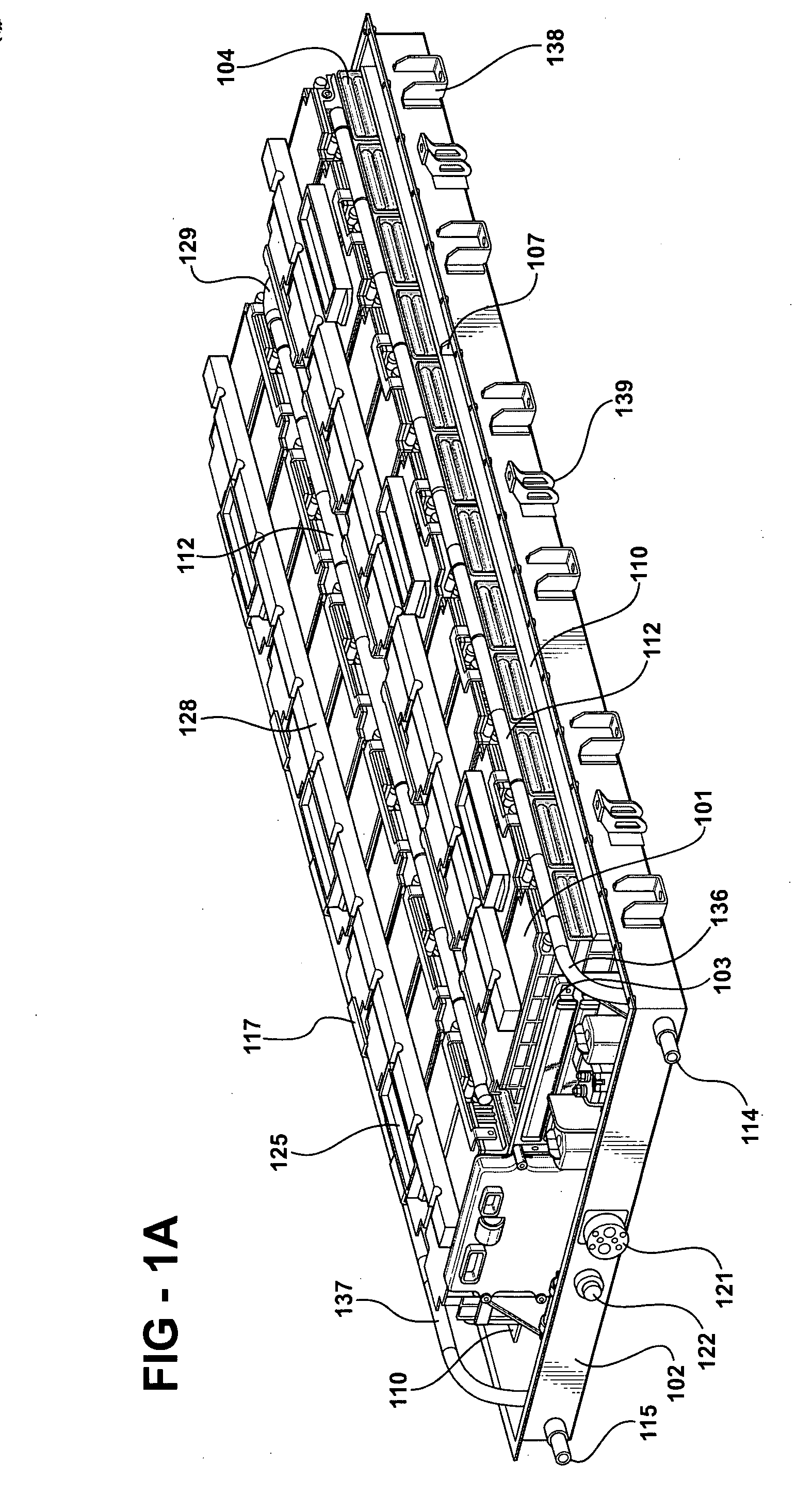
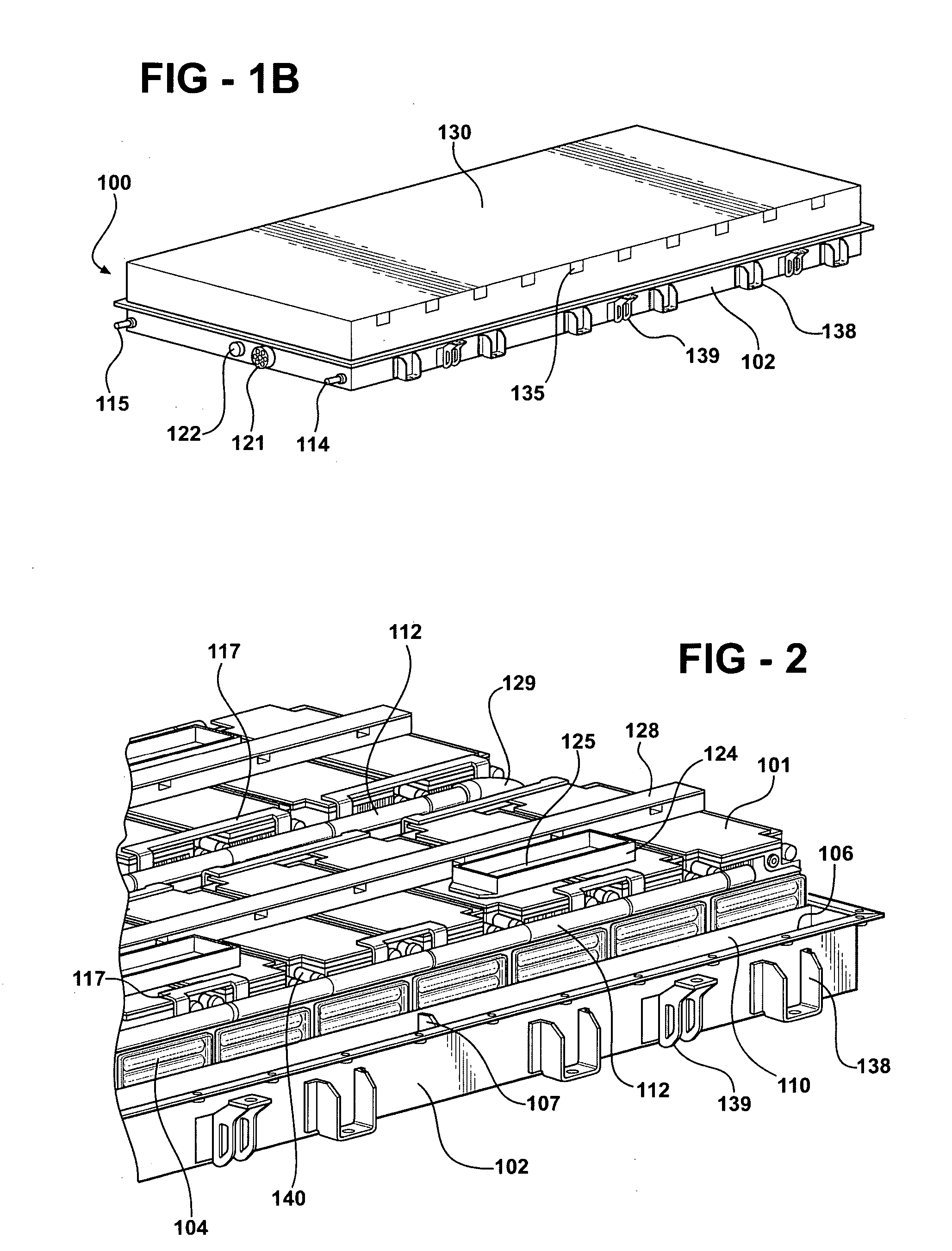
[0043] Disclosed herein is a modular battery system having a plurality of batteries, preferably monoblock batteries, interconnected electrically by bus bars and mechanically by rails and a cooling manifold. Referring to FIG. 1A, illustrated is an embodiment of a modular battery system, generally referred to as 100, wherein monoblock modules 101 are connected in series with bus bars 117. FIG. 1A illustrates a modular battery system comprised of twenty-four battery modules 101 electrically wired in series. The twenty-four battery modules 101 are arranged in a 12×2 array. The modular battery system may be set and secured in a system housing 102 with an integrated control unit (ICU) 103. The ICU 103 secures various components that may be utilized with a preferred embodiment of the system, as discussed below. Each module 101 is preferably secured between a pair of parallel rails. In this illustration, only the outside rail 110 is shown, however; for a view of both rails, refer to FIG. 5B...


PUM


Abstract

Disclosed herein is a modular battery system having at least one set of battery modules, preferably monoblock modules connected in series. Each of the battery modules may be designed with a first endplate and a second endplate, wherein each battery module is set between the first and second endplates and at least one band member couples the endplates to each other, binding the battery module between the endplates. The endplates are secured between a pair of rails and the system is disposed in a system housing. A cooling manifold provides a system wherein coolant flows into and out of each battery module. The system housing preferably has a coolant inlet and a coolant outlet. The cooling manifold is in flow communication with the coolant inlet and the coolant outlet. A battery monitoring system, which may include a battery control module and at least one remote sensing module, preferably monitors and collects performance and status information, such as voltage and temperature, of the battery modules. An integrated control unit (ICU) may be disposed in the system housing. The ICU supports electronics, some of which are used to collect electrical energy produced by the battery modules and / or monitor the system.

Description

FIELD OF THE INVENTION [0001] The instant invention relates generally to improvements in rechargeable high performance batteries, modules and packs. Specifically, the invention relates to multi-cell, monoblock batteries incorporated into a modular battery system. BACKGROUND OF THE INVENTION [0002] Rechargeable nickel-metal hydride (Ni-MH) batteries are used in a variety of industrial and commercial applications such as fork lifts, golf carts, uninterruptible power supplies, pure electric vehicles and hybrid electric vehicles. Vehicular applications include applications related to propulsion as well as applications related to starting, lighting and ignition. [0003] One aspect of battery operation that is particularly important for electric vehicle and hybrid vehicle applications is that of thermal management. In both electric and hybrid vehicle applications individual electrochemical cells are bundled together in close proximity. Many cells are both electrically and thermally coupled...

Claims


Application Information

Patent Timeline
IPC IPC(8): H01M10/04H01M10/50H01M50/112H01M50/207H01M50/244H01M50/262H01M50/264H01M50/276H01M50/278H01M50/28H01M50/505H01M50/51H01M50/569
CPCH01M2/0242H01M2/1077H01M2/206H01M10/345H01M10/4207H01M10/482H01M10/5004H01M10/5032H01M10/5057H01M10/5059H01M10/5075H01M2200/00H01M10/647H01M10/6556H01M10/6557H01M10/6567H01M10/613Y02E60/10H01M50/112Y02P70/50H01M50/278H01M50/276H01M50/51H01M50/569H01M50/244H01M50/262H01M50/264H01M50/207H01M50/505H01M50/28
Inventor BOURKE, DEBBIJOHNSON, HANS IANFREIMAN, JONATHAN LOCHERMELICHAR, ROBERT JOHNKARDITSAS, NICK
Owner BATTERY PATENT TRUST
Learn More