
Network system for safe connection of generation into a network power system

a network power system and network technology, applied in the field of network systems, can solve the problems of high cost of operation, network is not suited to export any power out of the network, and it is difficult to electrically connect distributed generation to the network power system

Inactive Publication Date: 2007-04-19
EATON CORP
View PDF12 Cites 21 Cited by
  • Summary
  • Abstract
  • Description
  • Claims
  • Application Information

AI Technical Summary

Benefits of technology

The present invention provides a network system for powering a plurality of network loads. The invention eliminates the need to bring current and voltage sensing wiring out of a network protector enclosure, reducing installation cost and complexity. The network system includes a network bus structured to power the network loads, power source feeders, a communication network, a generator, a generator protector relay, network protectors, and a controller. The controller receives power flow information from the network and determines if there is forward power flow through the network protectors to the network bus. The controller can de-energize the output relay to shut down the generator if there is no forward power flow through the network protectors. The controller can also adjust the power output from the distributed generators based on the predetermined setpoint and the predetermined count of the network protectors. The invention simplifies the installation process and reduces the complexity of the network system.

Problems solved by technology

Because of the inherent network characteristic of zero tolerance for any power flowing out of a network, a network is not suited to export any power out of the network.
This is the main reason why it has proven very difficult to electrically connect distributed generation to a network power system.
The cost of operation becomes an issue if the distributed generator can produce electrical energy or power at a lower total cost than the cost to acquire an equivalent amount of electrical energy or power from the grid.
The problem is, however, that should the amount of locally generated electrical energy or power approach or exceed the requirements of the connected load, then undesirable opening of one or more network protectors may occur, thereby negatively impacting the network reliability.
This condition is called “islanding” and is a very undesirable condition because it is inevitably associated with network outage due to inability of the islanded network to automatically synchronize with the utility in order to restore its normal operation.
This proposal is often called network underpower supervision and requires the connection of additional equipment to monitor for this condition and to control the operation of distributed generation, which is associated with significant costs.
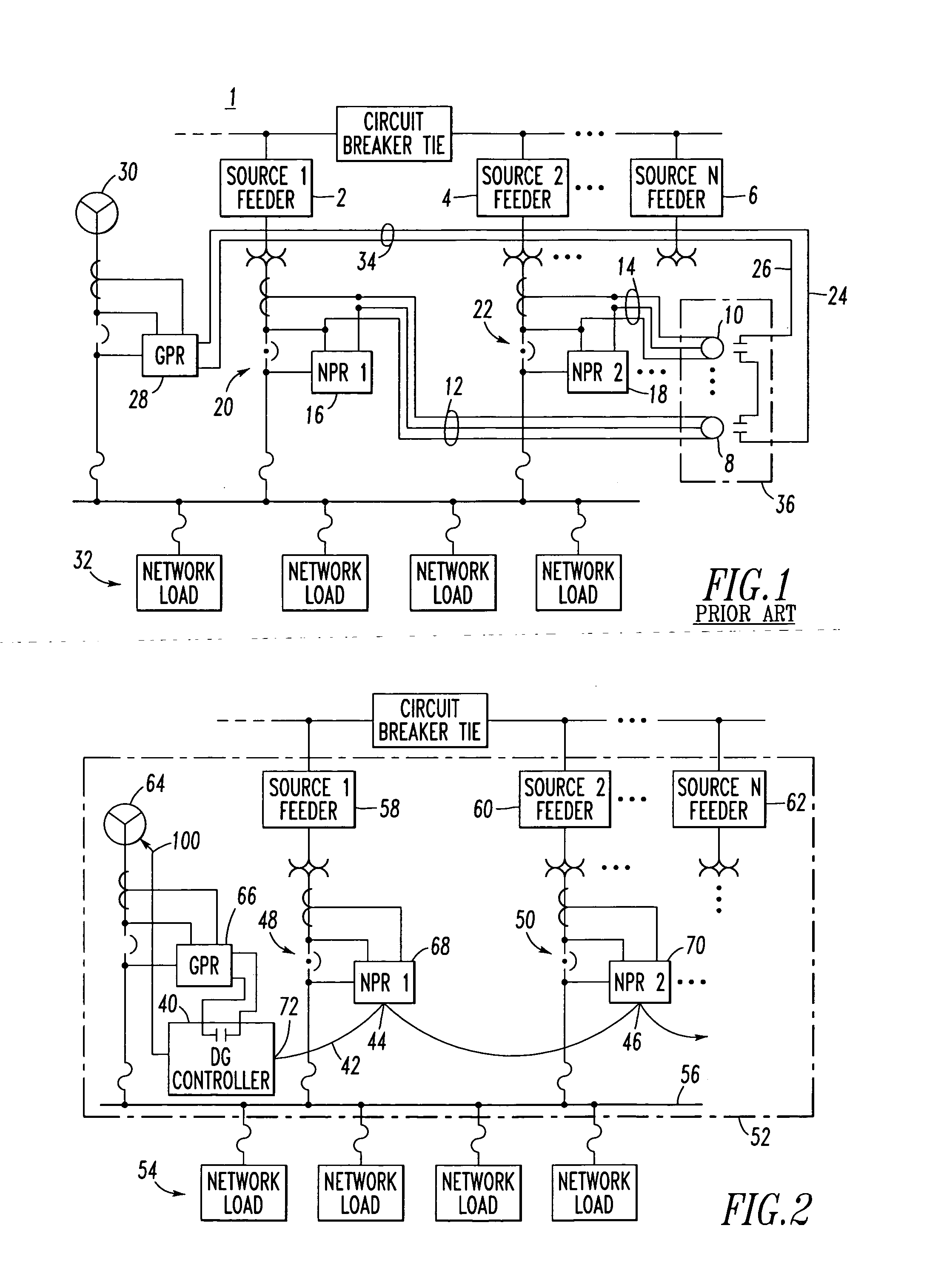
Hence, this system 1 entails significant costs.
An additional difficulty associated with the conventional voltage (potential) and current sensing circuits available with network protectors is that these circuits require that the wires be brought outside of the protection provided by the network protector enclosure.
Also, since the critical sensing wiring is being taken outside of the confines of the protected enclosure, those wires may be inadvertently opened or shorted.
Furthermore, for installations where the associated network protectors are not in the same immediate proximity, this issue becomes even more difficult to man age.
In the case of current sensing wiring, open-circuited wiring will not only break the signal to the network protector relay, thus, causing a malfunction within the network protector, it will also most likely permanently damage the current sensing transformer.
Replacing the current transformer requires a major repair operation that takes the network protector out of service for several hours.
For voltage sensing wiring, if the wiring is short circuited, then the voltage difference on the wires goes to zero resulting in a malfunction of the voltage sensing system within the network protector.
This is a critical problem since a main function of the network protector is to measure network and source voltage, compare them, and determine if it is safe to close the network protector or if the network protector should be opened.
Regardless of the case, the faulty sensing will impair the critical network protector functionality, which may escalate the abnormal condition and seriously impact the reliability of the entire installation.

Method used


Image

  • Network system for safe connection of generation into a network power system
  • Network system for safe connection of generation into a network power system
  • Network system for safe connection of generation into a network power system

Examples


example 1

[0033] The example communication network 42 includes a twisted pair, daisy chain among the interfaces 44,46 of the network protector relays 68,70 and the interface 72 of the controller 40.

example 2

[0034] The communication network 42 may be an INCOM network between the interfaces 44,46 of the network protector relays 68,70 and the interface 72 of the controller 40. Examples of the INCOM network and protocol are disclosed in U.S. Pat. Nos. 4,644,547; 4,644,566; 4,653,073; 5,315,531; 5,548,523; 5,627,716; 5,815,364; and 6,055,145, which are incorporated by reference herein. The network 42 or the controller 40 may include an uplink port (not shown) or communication port (not shown) to allow a supervisory system (not shown) to monitor the state of the various networked devices.

example 3

[0035] The interfaces 44,46 of the network protector relays 68,70 are associated with corresponding addresses. The controller processor 74 of FIG. 3 includes a polling table 76 and an auto-learning routine 78, which auto-learns at least some of the network protector relay interfaces, such as 44,46, on the communication network 42, and which adds the corresponding addresses of the interfaces of the network protector relays to the polling table 76. In this example, first, the distributed generation controller 40 powers up and auto-learns the nodes represented by communication-enabled network protectors 48,50 on the communication network 42. Then, after all nodes have been found, including displays, gateways and communication proxy servers (not shown), the addresses of those nodes are added to the polling table 76 along with the authenticated network protectors 48,50. Next, for the network protectors 48,50, the controller 40 polls each of those nodes, in order to read the corresponding...


PUM


Abstract

A network system includes a network bus structured to power plural network loads. A generator is structured to provide forward power flow to the network bus. A generator protector relay cooperates with the generator. Plural network protectors correspond to plural power source feeders, which are structured to provide forward power flow through corresponding network protectors to the network bus. Each network protector includes a network protector relay having an interface communicating power flow information to a communication network. A controller cooperates with the generator protector relay and includes an interface receiving the power flow information from the communication network and a processor determining whether there is forward power flow through the network protectors to the network bus. The processor enables the generator protector relay responsive to the forward power flow and reduces output from the generator responsive to the forward power flow being less than a predetermined amount.

Description

BACKGROUND OF THE INVENTION [0001] 1. Field of the Invention [0002] This invention pertains generally to network systems and, more particularly, to such network systems for powering a plurality of network loads through a plurality of power source feeders, one or more generators, and a network bus. [0003] 2. Background Information [0004] A network protector is a circuit breaker or other suitable switching device adapted to trip and open a power source, such as a feeder, upon detection of reverse power flow (i.e., power flowing through the power source and out of the network rather than into the network). Typically, overcurrent protection is provided by other devices, such as fuses in series with the network protector. The main function of the network protector is to automatically open upon detecting reverse power flow out of the network, and to close after the power from the respective power source has been restored. The overriding goal of a network system including plural network pr...

Claims


Application Information

Patent Timeline
Patent Type & Authority Applications(United States)
IPC IPC(8): H02H3/18
CPCH02H7/261
Inventor LOUCKS, DAVID G.KENNY, THOMAS J.BAIER, MARTIN
Owner EATON CORP
Learn More