
Spark plug and method for producing spark plug

Active Publication Date: 2007-04-12
NGK SPARK PLUG CO LTD
View PDF6 Cites 32 Cited by
  • Summary
  • Abstract
  • Description
  • Claims
  • Application Information

AI Technical Summary

Benefits of technology

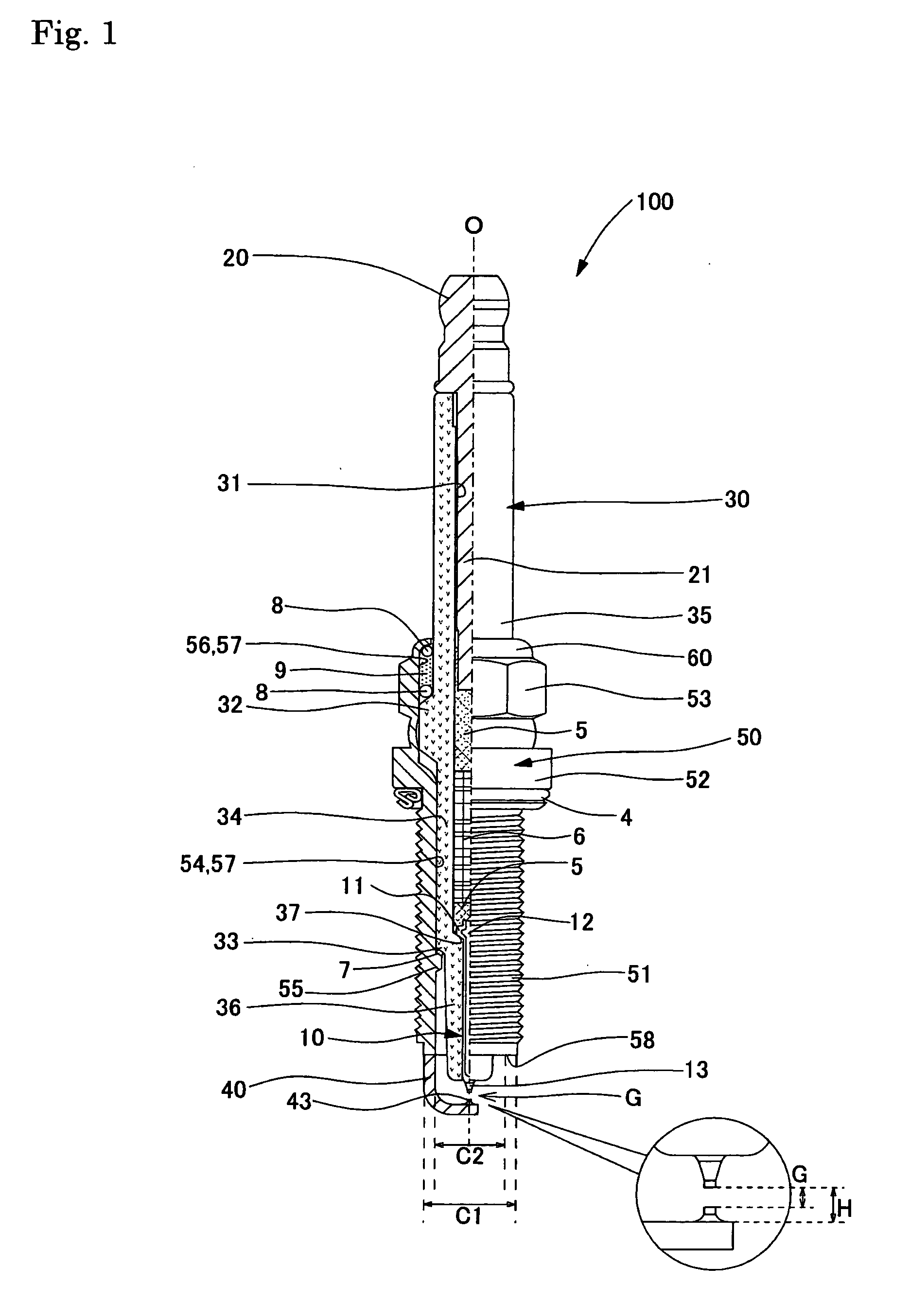
[0009] The invention has been conducted under the above-discussed various circumstances. It is an object of the invention to provide a small-diameter spark plug in which a noble metal tip is firmly joined to a round ground electrode to enhance the reliability, which comprises a ground electrode that has a flame developing property equivalent to that of the round ground electrode, that is enabled to have a prolonged lifetime, and that has an excellent heat dissipation property. It is another object of the invention to provide a method which enables the production of such a spark plug to be performed without unnecessarily increasing the production cost and the man-hours.
[0038] As in the eleventh configuration, when, in the side face of the round ground electrode, the radius curvature RA of the inner side face of the portion to which the noble metal tip is to be joined (corresponding to the section A) is set to be equal to or larger than the radius curvature RB of the inner side face of the portion to which the noble metal tip is not to be joined (corresponding to the section B), the following effects can be expected. When the noble metal tip is pressed, the butting area of the near-center portion where the lower face of the noble metal tip and the side face of the round ground electrode are contacted with each other is increased. In resistance welding, for example, this causes the portion which melts in an initial stage of the resistance welding, to become larger than that in the conventional art. Therefore, the welding property is improved, and the defect that joining is performed in “floating state” can be reduced. Also when laser welding is conducted, the distance by which the side face of the round ground electrode is separated from the lower face of the noble metal tip can be shortened, and hence more stable joining is enabled. It is a matter of course that it is more preferable to set RA>RB while excluding RA=RB.

Problems solved by technology

As described above, however, it is not easy to sufficiently ensure the thickness of the tip end face of the metal shell to which the ground electrode is to be joined.
In the case of a round ground electrode, however, the electrode has a circular section shape, and hence its diameter is allowed only to have a value corresponding to the thickness of the tip end face of the metal shell, with result that it is difficult to ensure a sufficient heat dissipation property.
According to this configuration, however, the number of production man-hours is inevitably increased.
Since the outline of a round ground electrode is arcuately bent, it is not easy to firmly join a noble metal tip which is formed into a substantially columnar shape having a flat face at the upper and lower ends, to the electrode.
However, there is a problem in that this configuration is not practical because of increases of the production cost and man-hours, and difficulty in facing of the noble metal tip.
Since the noble metal tip is formed into a columnar shape having a flat face at the upper and lower ends, it is not easy to realize firm joining with the round ground electrode having the arcuate face.
As a result, even when irradiation with a laser beam is conducted, the degree of penetration between the round ground electrode and the noble metal tip is low.
Also in this case, consequently, firm joining is hardly realized.

Method used


Image

  • Spark plug and method for producing spark plug
  • Spark plug and method for producing spark plug
  • Spark plug and method for producing spark plug

Examples


first embodiment

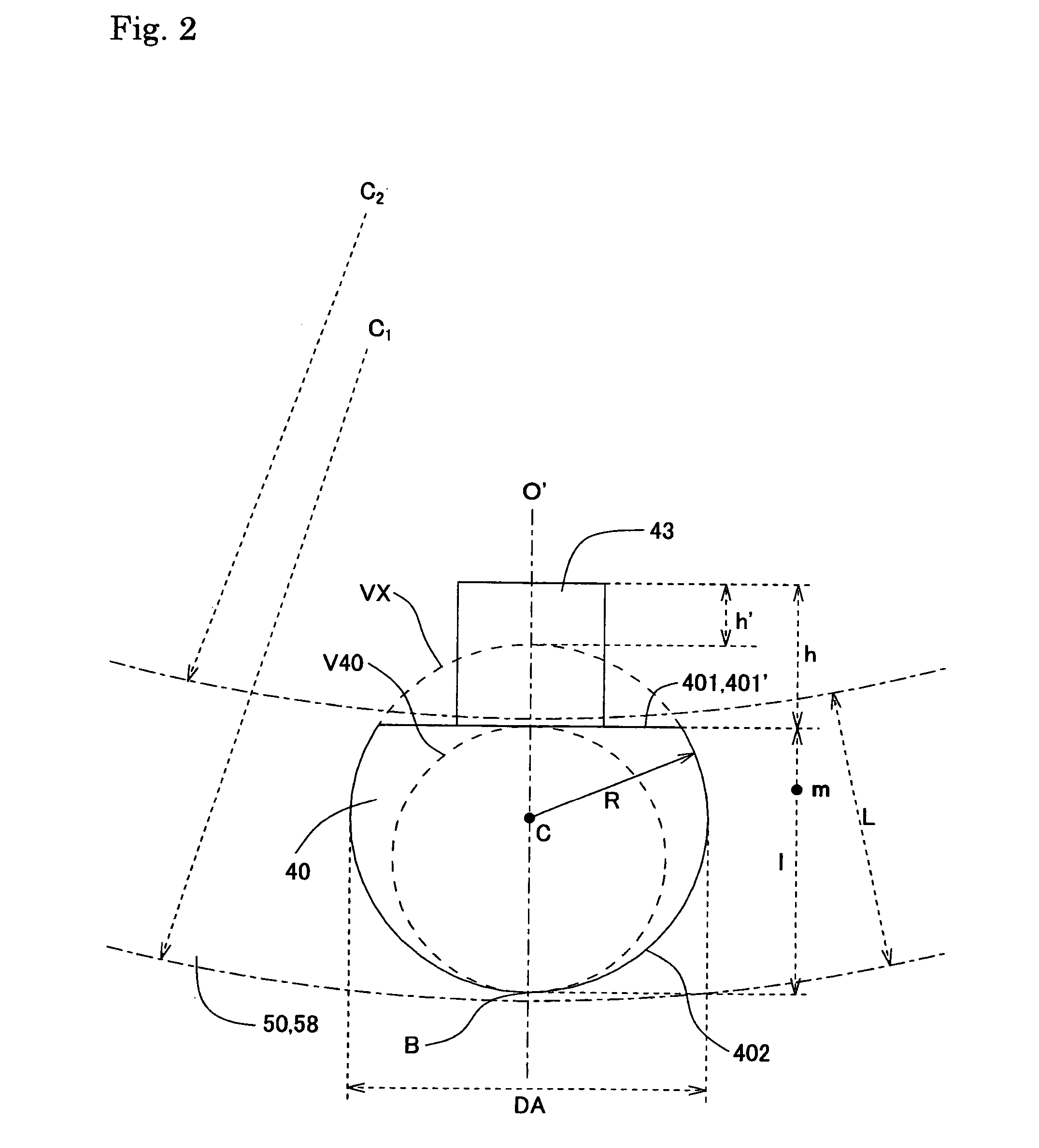
[0067] As shown in FIG. 2, when viewed in the extending direction of the ground electrode 40 (corresponding to the front-and-back direction of the plane of the paper), the outline of the ground electrode is formed by: a flat face 401 formed as a linear portion 401′ on the side of the center electrode 10 (the upper side of the drawing); and an arcuate portion 402 which draws an arc that is continuous to the both ends of the linear portion 401′, and that has a radius curvature R. In the first embodiment, the arcuate portion 402 is an arc through which the both ends of the linear portion 401′ are connected to each other, and which has a constant radius curvature. In other words, a shape which is obtained by cutting away the side face of the columnar ground electrode which is on the side of the center electrode 10 is formed. The linear portion 401′ and the flat face 401 correspond to “inner side face” in the invention.

[0068] The distance (indicated by 1 in FIG. 2) between the linear por...

third embodiment

[0084] Next, the third embodiment shown in FIG. 6 will be described.

[0085] As shown in FIG. 6, when viewed in the extending direction of the ground electrode 40 (corresponding to the front-and-back direction of the plane of the paper), the outline of the ground electrode is formed by: a flat face 3401 formed as a linear portion 3401′ on the side of the center electrode 10 (the upper side of the drawing); and inner arcuate portions 3402 which draw a substantially one-quarter arc on the both ends of the linear portion 3401′ having a radius curvature r. Furthermore, an outer arcuate portion 3403 which draws an arc having a radius curvature R (>r) is formed so as to connect the ends of the arcs of the inner arcuate portions 3402 which are on the both sides of the outer arcuate portion. The inner arcuate portions 3402 and the outer arcuate portion 3403 correspond to “first arcuate portions” and “second arcuate portion” in the invention, respectively.

[0086] The value which can be taken b...

sixth embodiment

[0106] Next, a sixth embodiment will be described.

[0107] As shown in FIG. 9A, the ground electrode 40 has a columnar shape of a substantially true circle, and also the outer tip 43 has a columnar shape of a substantially true circle. As shown in the enlarged view of FIG. 9B, the portion of the ground electrode 40 to which the outer tip 43 is to be joined, and the periphery of the portion are divided into a section A which is slightly wider than the width of the outer tip 43, and which has a larger radius curvature, and a section B which excludes the section A, and which has a smaller radius curvature. The radius curvature of the section B is substantially equal to the radius of the ground electrode 40. For the sake of description, the outline of the ground electrode 40 is shown with exaggeration in FIG. 9B. The state after the joining between the ground electrode 40 and the outer tip 43 is indicated together with the molten portion by broken lines.

[0108] Referring to FIG. 9B, the s...


PUM


Abstract

A spark plug comprising: a center electrode extending in a direction of an axis of said spark plug; a cylindrical insulator which has a shaft hole, and which holds said center electrode in said shaft hole in a state where a tip end of said center electrode is projected from a tip end face of said insulator; a metal shell which holds said insulator; and a ground electrode in which one end is joined to a tip end face of said metal shell, and which extends from said one end toward another end, wherein said ground electrode has an inner side face which faces said center electrode, and an outer side face which is a back face with respect to said inner side face, said outer side face is formed as an arcuately curved face when viewed from a side of said another end in an extending direction of said ground electrode, and a columnar noble metal tip is joined to said inner side face.

Description

FIELD OF THE INVENTION [0001] The present invention relates to a spark plug which is to be mounted on and used in an internal combustion engine, and more particularly to a spark plug which realizes an excellent flame developing property. BACKGROUND OF THE INVENTION [0002] A spark plug is used as an ignition device which performs a spark discharge while using a gap between a center electrode and a ground electrode that are exposed in a combustion chamber of an internal combustion engine, as a spark discharge gap. Conventionally, in order to realize a prolonged lifetime of a spark plug, a tip of a noble metal alloy (hereinafter, also referred to merely as noble metal tip) which is excellent in spark wear resistance and resistance to oxidation at high temperatures (hereinafter, the spark wear resistance and the resistance to oxidation at high temperatures are often referred in combination as durability) is joined to a tip end portion(s) of one or both of the electrodes which will funct...

Claims


Application Information

Patent Timeline
IPC IPC(8): H01T13/20
CPCH01T13/32H01T21/02
Inventor TORII, KAZUYOSHIYOSHIDA, KAZUMASAMATSUTANI, WATARU
Owner NGK SPARK PLUG CO LTD
Learn More