Tear propagation resistant film-backed adhesive tape
a film-backed adhesive tape and tear propagation resistance technology, which is applied in the direction of film-backed adhesives, paper/cardboard containers, transportation and packaging, etc., can solve the problems of reducing the tear propagation resistance of adhesive tape backing materials, glass filaments, for example, are not resistant to crease fracture,
- Summary
- Abstract
- Description
- Claims
- Application Information
AI Technical Summary
Benefits of technology
Problems solved by technology
Method used
Image

Examples
Embodiment Construction
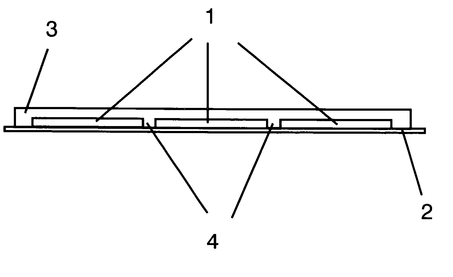
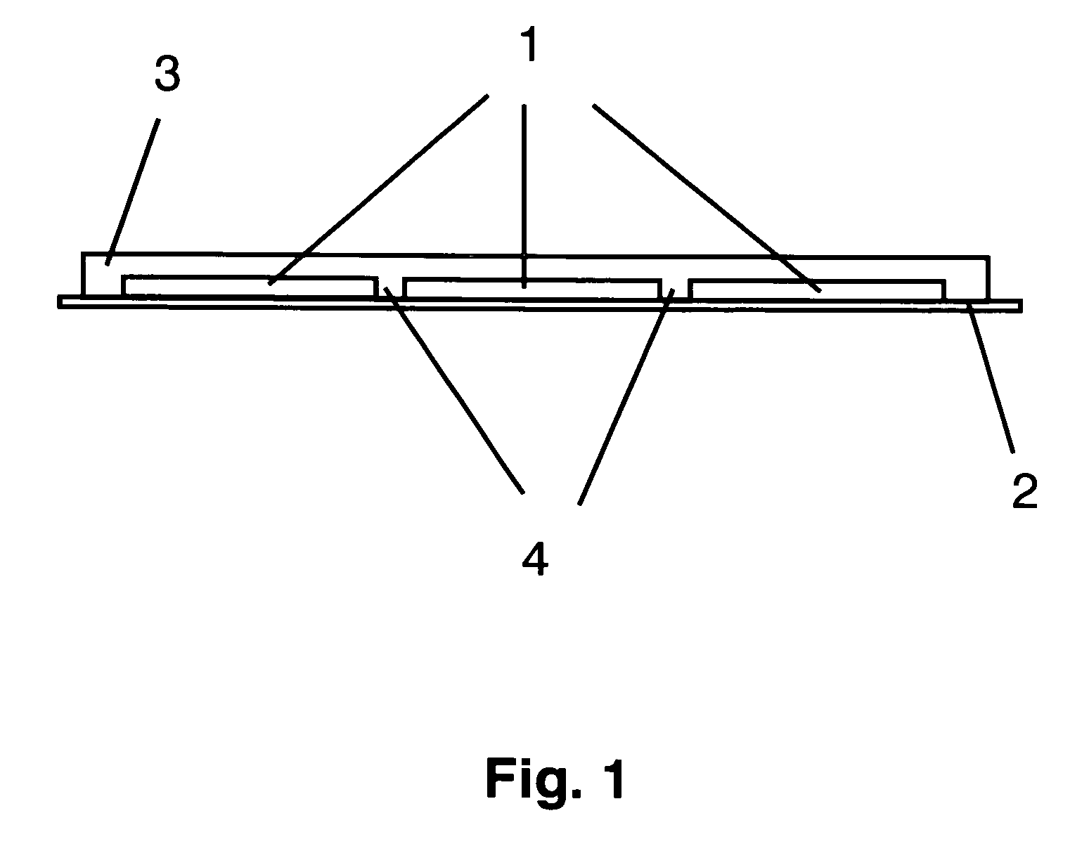
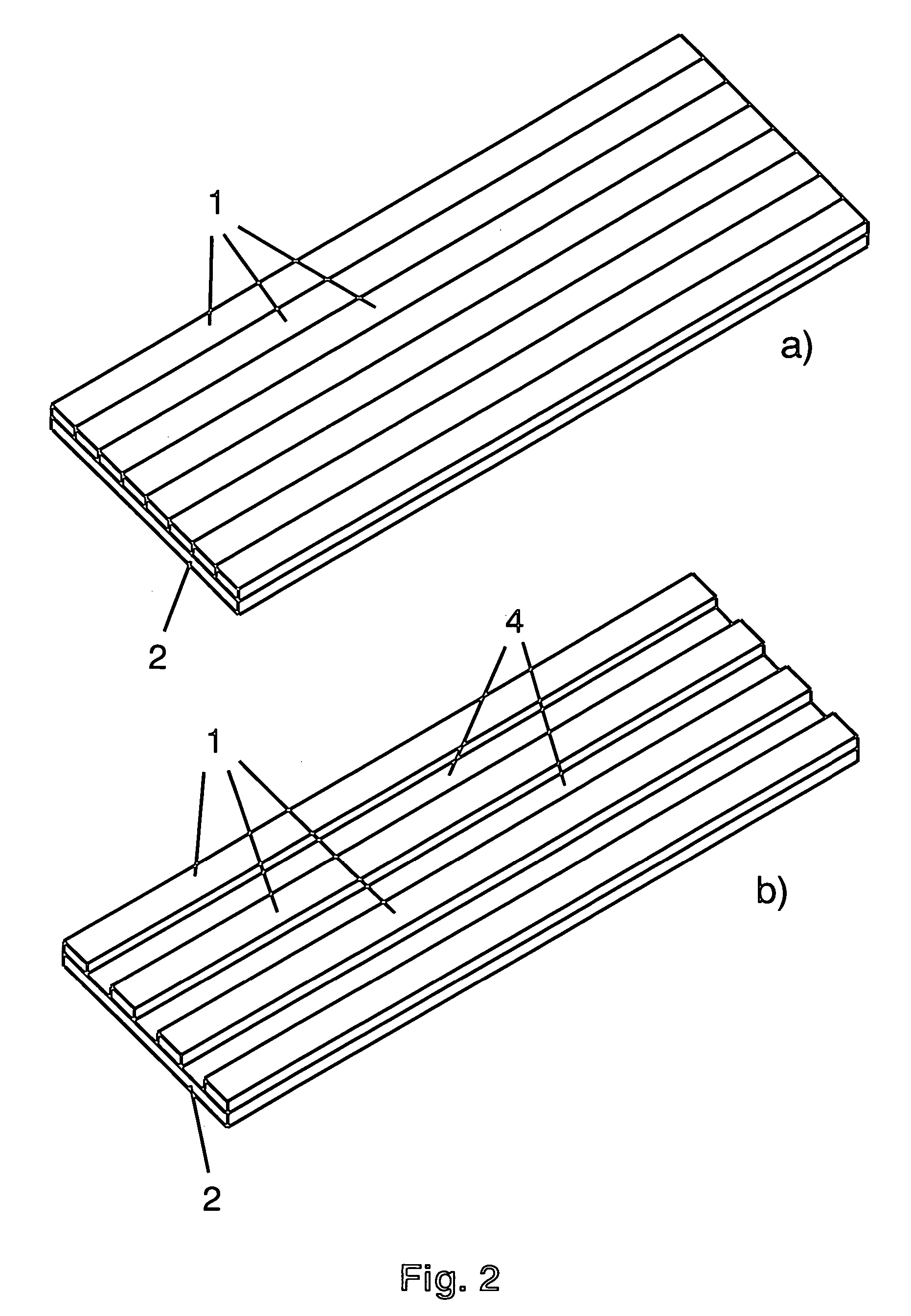
[0008] The underlying adhesive tape here is similar in its tensile strength to a film-backed adhesive tape with a conventionally oriented monofilm. Furthermore, as a result of the production of numerous intact and undamaged film side edges across the width of the adhesive tape, the present invention allows the necessary tear propagation resistance. With its side edge undamaged, an adhesive tape with an oriented film backing such as MOPP, for example, has good tear resistance. However, if the side edge has been damaged, deliberately or unintentionally, the tear propagation resistance is low. In the present invention, in the event of side damage, one of the edges located further in the interior of the adhesive tape replaces the damaged outer edge and so places the adhesive tape back into a state in which it is undamaged, as it were, for the rest of the remaining backing width.
[0009] The backing of the adhesive tape of the invention is composed accordingly of a composite of polymer ma...
PUM
| Property | Measurement | Unit |
|---|---|---|
| Electrical resistance | aaaaa | aaaaa |
| Sensitivity | aaaaa | aaaaa |
Abstract
Description
Claims
Application Information
 - R&D
- Intellectual Property
- Life Sciences
- Materials
- Tech Scout
- Unparalleled Data Quality
- Higher Quality Content
- 60% Fewer Hallucinations
Browse by: Latest US Patents, China's latest patents, Technical Efficacy Thesaurus, Application Domain, Technology Topic, Popular Technical Reports.
© 2025 PatSnap. All rights reserved.Legal|Privacy policy|Modern Slavery Act Transparency Statement|Sitemap|About US| Contact US: help@patsnap.com