Safety syringe

a safety syringe and syringe technology, applied in the field of safety syringes, can solve the problems of high manufacturing cost of conventional safety syringes, complicated safety syringes, waste of medication,

Inactive Publication Date: 2007-04-05
LINFAIR ENG HK
View PDF2 Cites 23 Cited by
  • Summary
  • Abstract
  • Description
  • Claims
  • Application Information

AI Technical Summary

Benefits of technology

[0013] The primary objective of the present invention is to provide a safety syringe is able to avoid a needle hurting people after the syringe is used.
[0014] The safety syringe has an inner barrel, an outer barrel and a locking hub. The inner barrel is mounted removably in the outer barrel and has a front. The outer barrel has a rear opening, an inner surface and an annular detent. The annular detent is formed on the inner surface. The locking hub is mounted on front of the inner barrel and has a proximal end, a distal end, a needle mounted on the distal end and a flange formed around and protruding from the proximal end of the locking hub. After an injection, the inner barrel is pulled out of the outer barrel, and the flange around the locking hub engages the annular detent in the outer barrel. When the inner barrel separates from the outer barrel, the locking hub with the needle stays inside the outer barrel. The safety syringe has fewer parts so its design is simple. Furthermore, less medication is wasted because the locking hub is the only component between the inner barrel and the needle.

Problems solved by technology

However, the conventional safety syringe is complicated and wastes medication.
The complexity of the conventional safety syringe causes the conventional safety syringe to be expensive to manufacture.
The medication in the retractor (7) and the locking hub (9) is wasted and may represent a significant expense when the medication is expensive.

Method used


Image

  • Safety syringe
  • Safety syringe
  • Safety syringe

Examples


Embodiment Construction

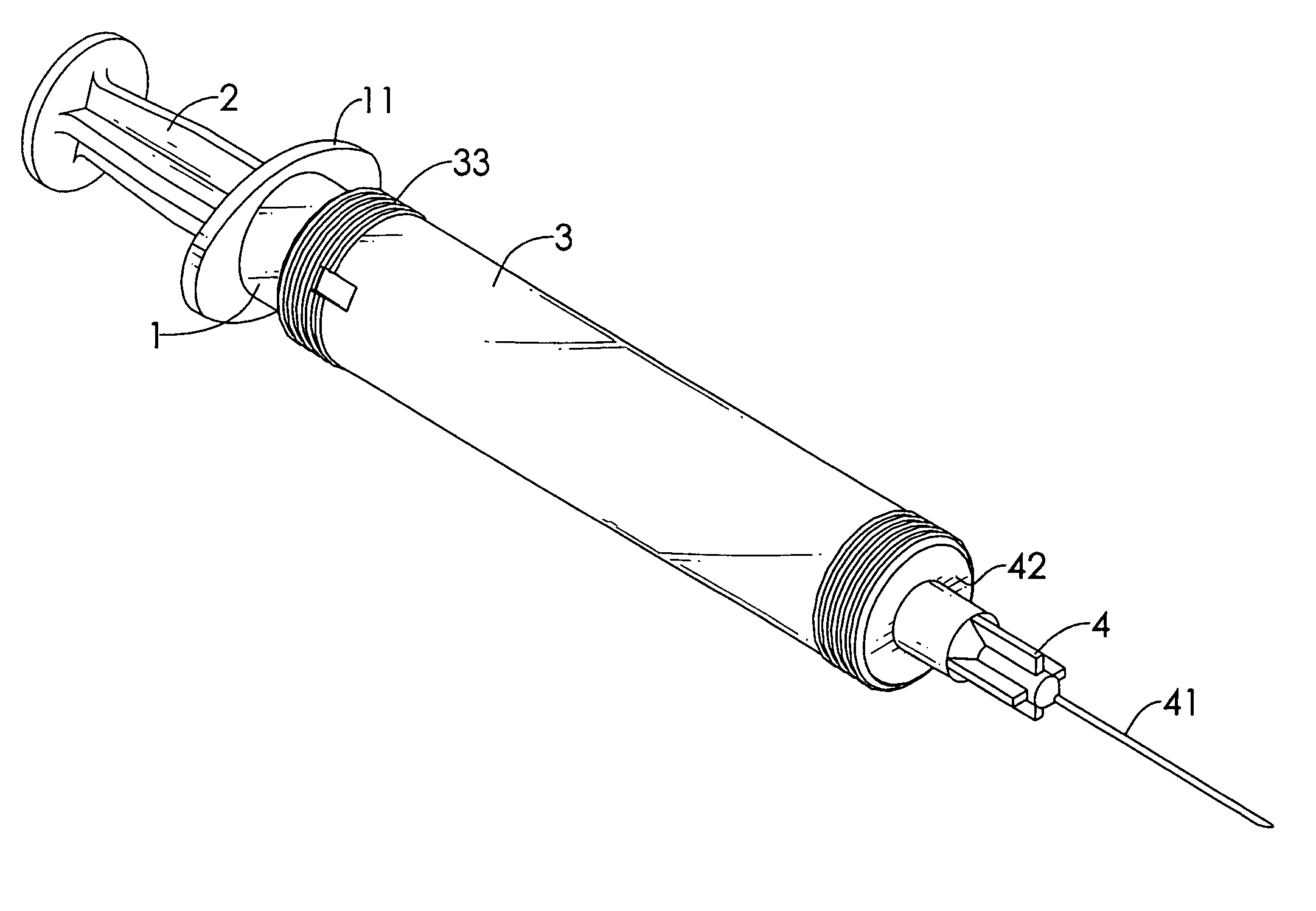
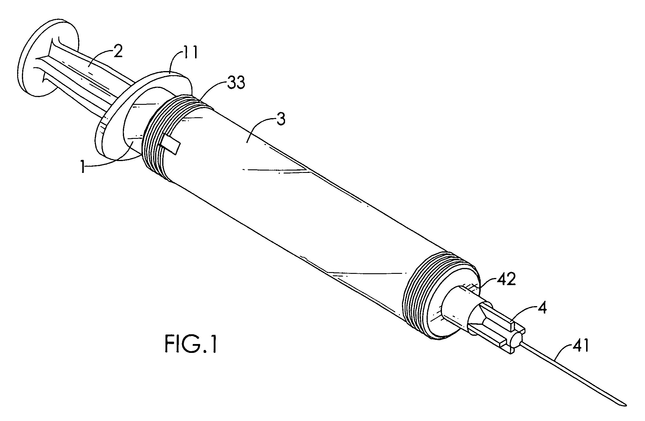
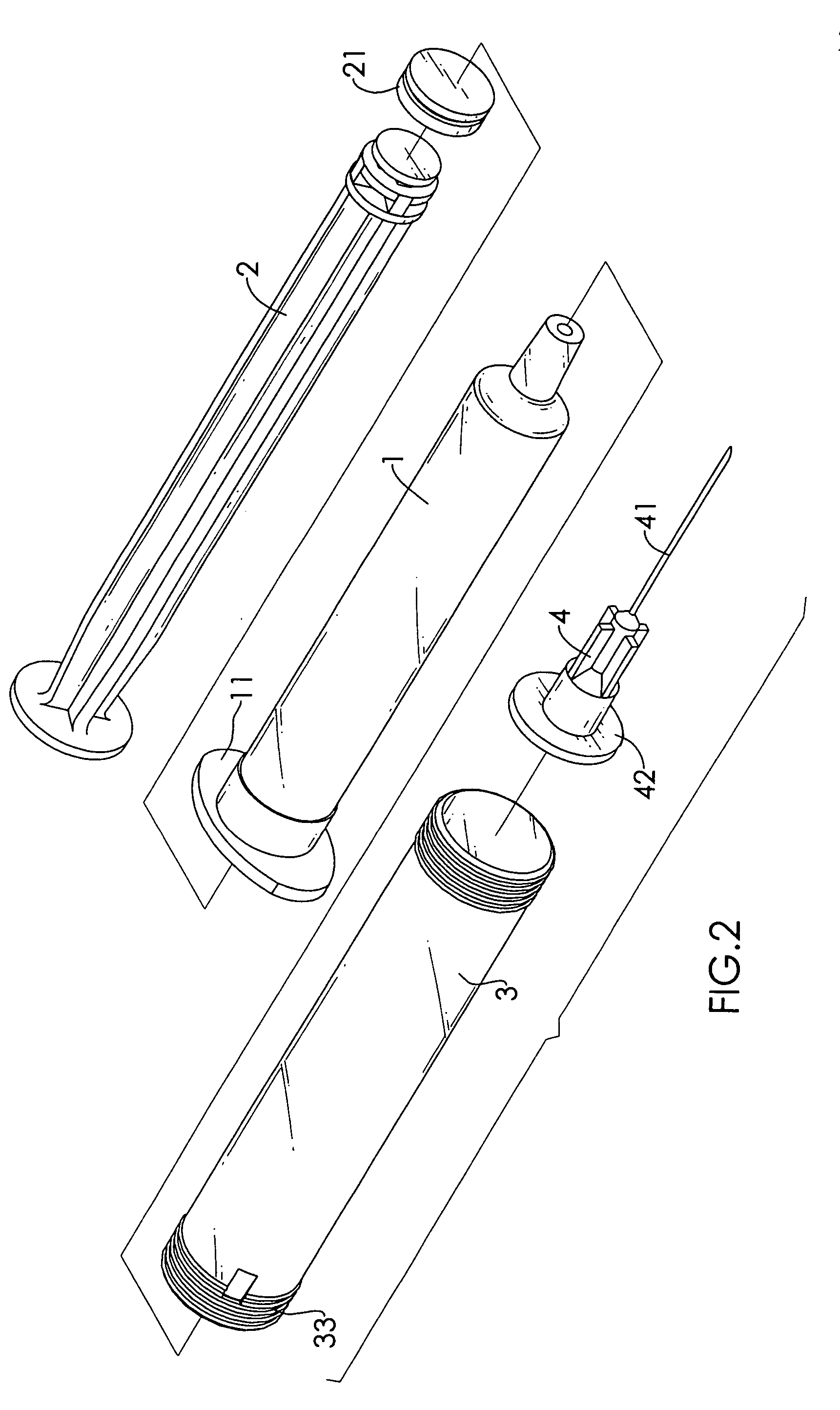
[0024] With reference to FIGS. 1, 2 and 3, a safety syringe in accordance with the present invention comprises an inner barrel (1), a plunger (2), an outer barrel (3) and a locking hub (4).

[0025] The inner barrel (1) may hold medication and has a front opening, a rear opening, an outside surface and a finger flange (11). The finger flange (11) is formed on and protrudes out from the outer surface near the rear opening and may have multiple lobes formed opposite to each other.

[0026] The plunger (2) extends slidably into the inner barrel (1) through the rear opening and has a front end and a piston (21). The piston (21) is attached to the front end of the plunger (2) and slides inside the inner barrel (1). When the plunger (2) is pushed into the inner barrel (1), medication in the inner barrel (1) is discharged.

[0027] The outer barrel (3) is mounted removably on the inner barrel (1) and has a front opening, a rear opening, an outer surface, an inner surface, an annular detent (31),...


PUM


Abstract

A safety syringe has an inner barrel, an outer barrel and a locking hub. The inner barrel is mounted removably in the outer barrel and has a front opening. The outer barrel has an inner surface and an annular detent formed in the inner surface. The locking hub is mounted on front opening and has a proximal end, a distal end, a needle mounted on the distal end and a flange formed around and protruding from the proximal end. After an injection, the inner barrel is pulled out of the outer barrel and the flange engages the annular detent. When the inner barrel separates from the outer barrel separate, the locking hub with the needle stays inside the outer barrel. The safety syringe has fewer parts so the design is simple. Less medication is wasted because the locking hub is the only component between the inner barrel and the needle.

Description

BACKGROUND OF THE INVENTION [0001] 1. Field of the Invention [0002] The present invention relates to a syringe, and more particularly to a safety syringe that keeps people from being injured by the syringe after the syringe is used. [0003] 2. Description of Related Art [0004] With reference to FIGS. 7 and 8, a conventional safety syringe comprises an inner barrel (5), a plunger (6), a retractor (7), a locking hub (9) and an outer barrel (8). [0005] The inner barrel (5) selectively hold liquid medication and has a front opening and a rear opening. [0006] The plunger (6) has a front and a piston (61). The piston (61) is mounted on the front of the plunger (6) and slidably in the inner barrel (5) through the rear opening. When the plunger (6) pushes into the inner barrel (5), the piston (61) pushes medication out of the inner barrel (5). [0007] The retractor (7) is mounted removably on the front opening of the barrel (5) and has an outer edge, multiple resilience fingers (71) and a fro...

Claims


Application Information

Patent Timeline
Patent Type & Authority Applications(United States)
IPC IPC(8): A61M5/32A61M5/00
CPCA61M5/3243A61M2005/3253
Inventor LEE, CHIEN-YUAN
Owner LINFAIR ENG HK
Why Eureka
Try Eureka