
Multiple exposure optical imaging apparatus

a multi-exposure, optical imaging technology, applied in the field of digital cameras, can solve the problems of reducing the signal-to-noise ratio of the camera, unable to reduce the state of the art light sensor, and unable to achieve the effect of reducing the effective number of pixels and increasing the spatial resolution

Inactive Publication Date: 2007-04-05
LUCENT TECH INC
View PDF3 Cites 34 Cited by
  • Summary
  • Abstract
  • Description
  • Claims
  • Application Information

AI Technical Summary

Benefits of technology

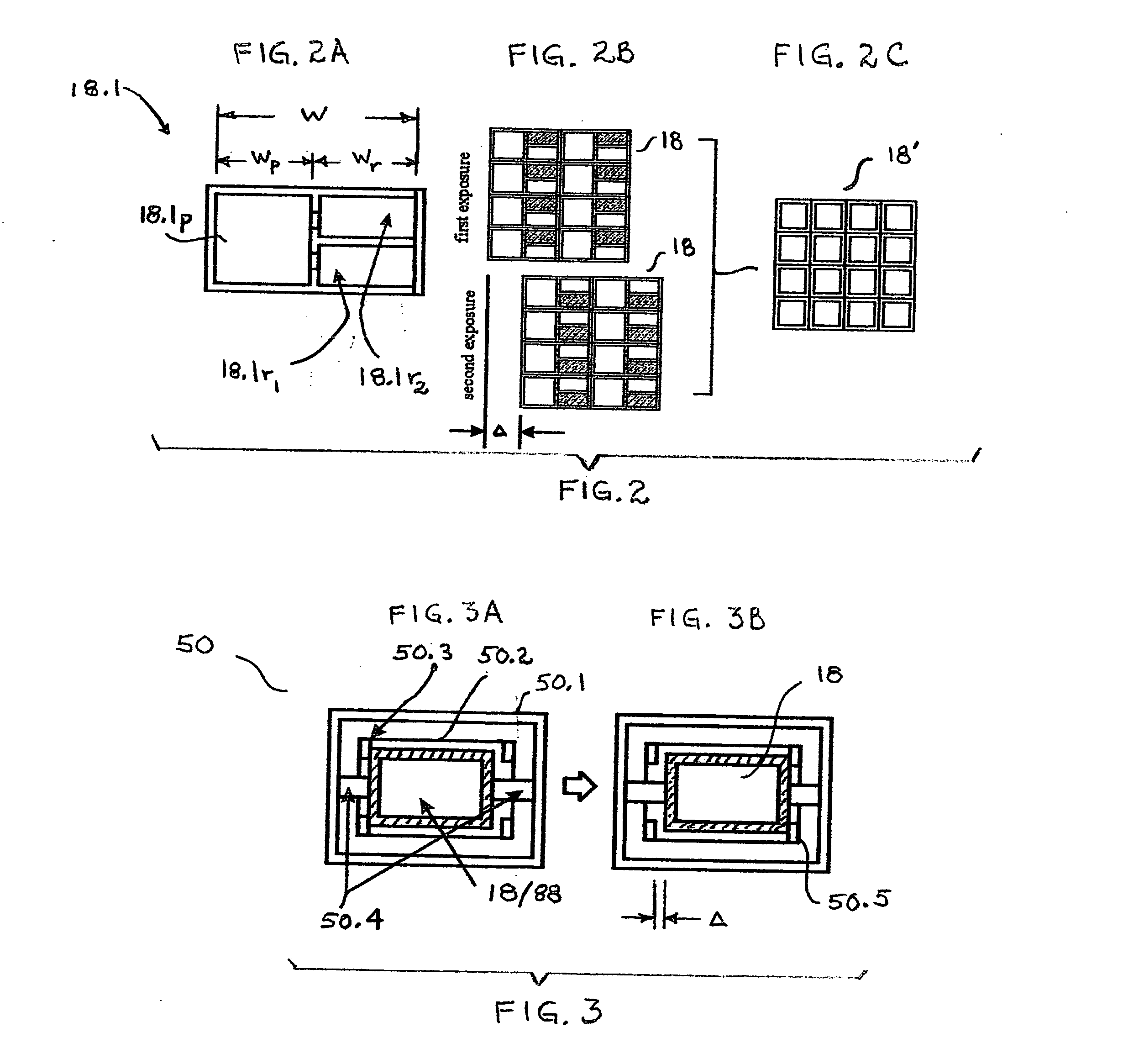
[0010] In this fashion, we increase spatial resolution by increasing the effective number of pixels of the sensor without increasing the actual number of pixels. Thus, a sensor with only N pixels has the effective resolution of a sensor having 2N pixels.

Problems solved by technology

However, smaller pixels collect fewer photons, which decreases the camera's signal-to-noise ratio.
Nevertheless, the state of the art light sensor is still limited by both the shot noise in the collected photons and the electronic noise of the converter circuits.
The shot noise of light is fundamental and cannot be reduced, whereas the electronic noise can be reduced by cooling the sensor, albeit at the expense of increased power consumption.
Thus, there is a practical limit to the number of pixels that can be put in the typical area of a SLR camera.

Method used


Image

  • Multiple exposure optical imaging apparatus
  • Multiple exposure optical imaging apparatus
  • Multiple exposure optical imaging apparatus

Examples


Embodiment Construction

Digital Camera Configuration

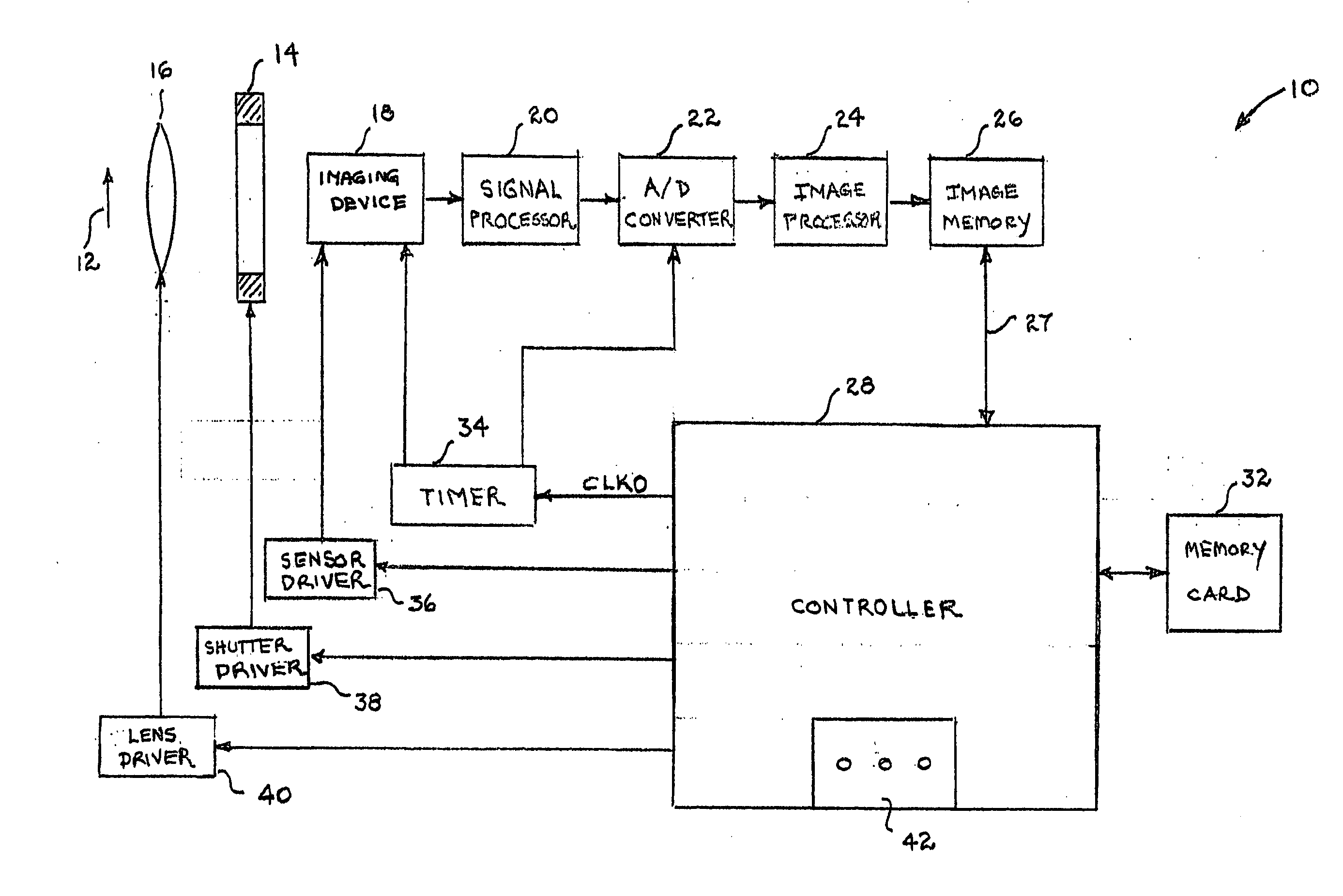
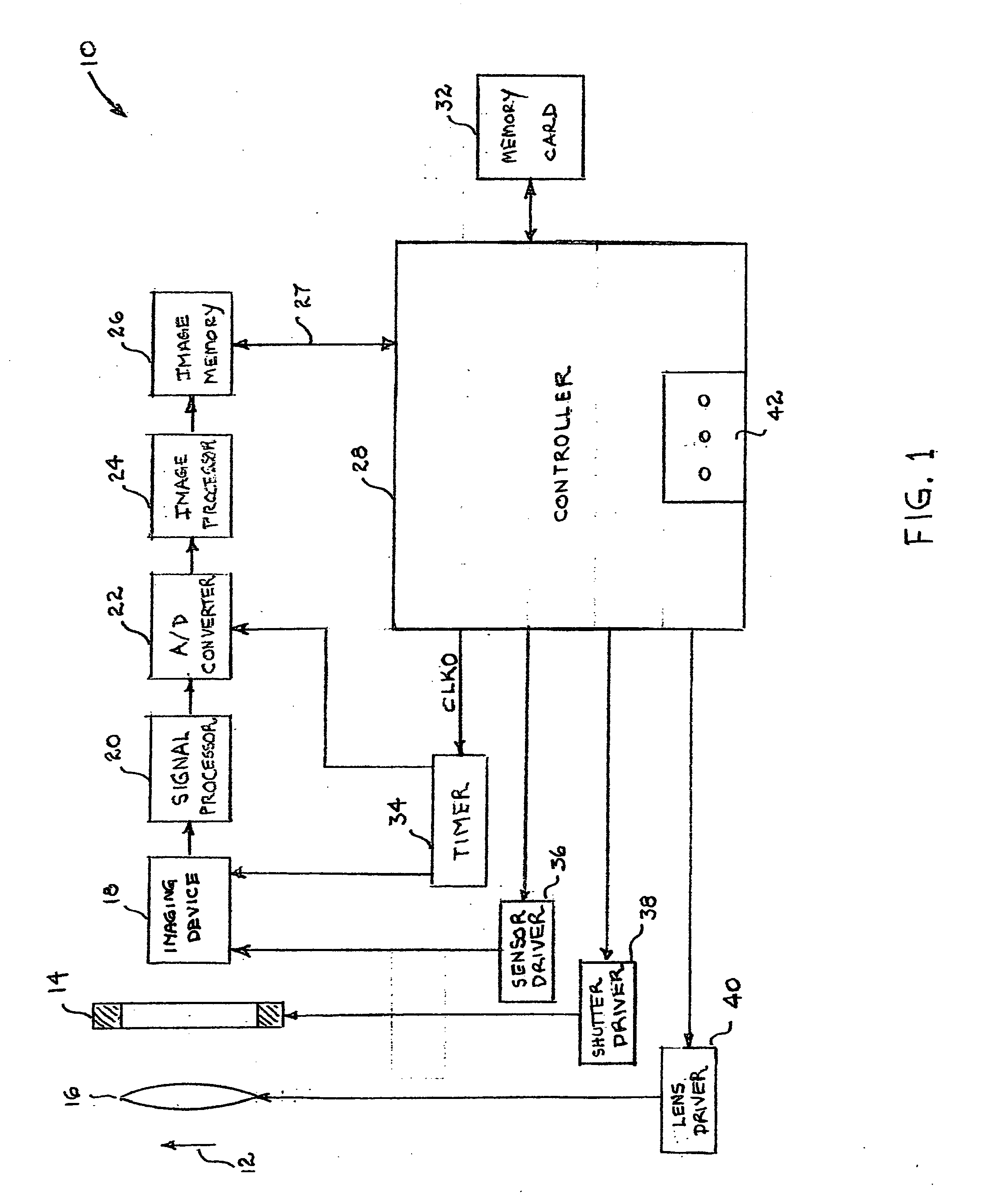
[0020] Before discussing our invention in detail, we turn first to FIG. 1, which shows a block diagram of a well-known optical imaging apparatus 10 for generating and storing or recording electronic data representing an optical image of an object 12. (By the term object we mean anything from which light emanates by a process of, for example, reflection, refraction, scattering, or internal generation.) For simplicity we will assume in the following discussion that apparatus 10 is a digital camera comprising a shutter 14 for alternately blocking light from image 12 from entering the camera or transmitting such light into the camera. Such digital cameras are well known to have the capability of generating still images, video images, or both.

[0021] When the shutter 14 is open, light from object 12 is focused by a lens system 16 onto an imaging device 18. The lens system typically includes a zoom lens subsystem, a focusing lens subsystem and / or an image shi...


PUM


Abstract

Apparatus for storing an optical image of an object comprises an imaging device having a multiplicity of pixels, each pixel including a light sensor and a multiplicity of storage cells coupled to the sensor. A lens system focuses light from the object onto the imaging device. Within each pixel a first one of its storage cells is configured to store data corresponding to a first exposure of its sensor to light from the object, and a second one of its storage cells is configured to store data corresponding to a second exposure of its sensor to light from the object. In a preferred embodiment, the pixels are arranged in an array extending along a first direction, and during the time interval between the first and second exposures, a translator is configured to produce, in a second direction, a relative translation or shift between the imaging device and the focal point of the lens system. In one embodiment, the second direction is traverse to the first direction. In a preferred embodiment, each pixel comprises a photosensitive region, and the pixels are shifted by a distance that is approximately equal to one half the pitch of the photosensitive regions as measured in the second direction. In this fashion, the invention increases the spatial resolution by increasing the effective number of pixels of the sensor without increasing the actual number of pixels. In alternative embodiment of the invention, the dynamic range of the sensor is enhanced.

Description

BACKGROUND OF THE INVENTION [0001] 1. Field of the Invention [0002] This invention relates to apparatus for storing optical images in electronic form and, more particularly, to digital cameras for storing either still images, video images, or both. [0003] 2. Discussion of the Related Art [0004] The trend in the development of digital cameras is to increase spatial resolution by increasing the number of pixels in the camera's image converter. The converter is a form of light detection sensor, typically a charge coupled device (CCD) or complementary metal oxide semiconductor (CMOS) device. For a given size light sensor [e.g., the 24 mm×36 mm sensor area of a standard single lens reflex (SLR) camera], increasing the number of pixels implies reducing the size of each pixel. However, smaller pixels collect fewer photons, which decreases the camera's signal-to-noise ratio. It is known that this problem can be alleviated in several ways: by using a micro-lens array to increase light collec...

Claims


Application Information

Patent Timeline
IPC IPC(8): H01L27/00H04N5/349H04N5/355
CPCH04N3/155H04N3/1587H04N5/349H04N5/35581H04N5/372H04N25/48H04N25/589H04N25/71
Inventor GATES, JOHN VANATTANUZMAN, CARL JEREMYPAU, STANLEY
Owner LUCENT TECH INC
Learn More