Method of surface treatment of composite material structures with atmospheric plasma beams
a composite material and atmospheric plasma technology, applied in the direction of surface pretreatment, cleaning process and apparatus, chemical instruments and processes, etc., can solve the problems of low surface energy, difficult wet and bonding of polymeric surfaces, and energy consumption, so as to improve the general performance of these structures, increase the surface energy and wettability, and increase the mechanical properties of adhesive bonds
Inactive Publication Date: 2007-04-05
AIRBUS OPERATIONS SL
View PDF6 Cites 13 Cited by
- Summary
- Abstract
- Description
- Claims
- Application Information
AI Technical Summary
Benefits of technology
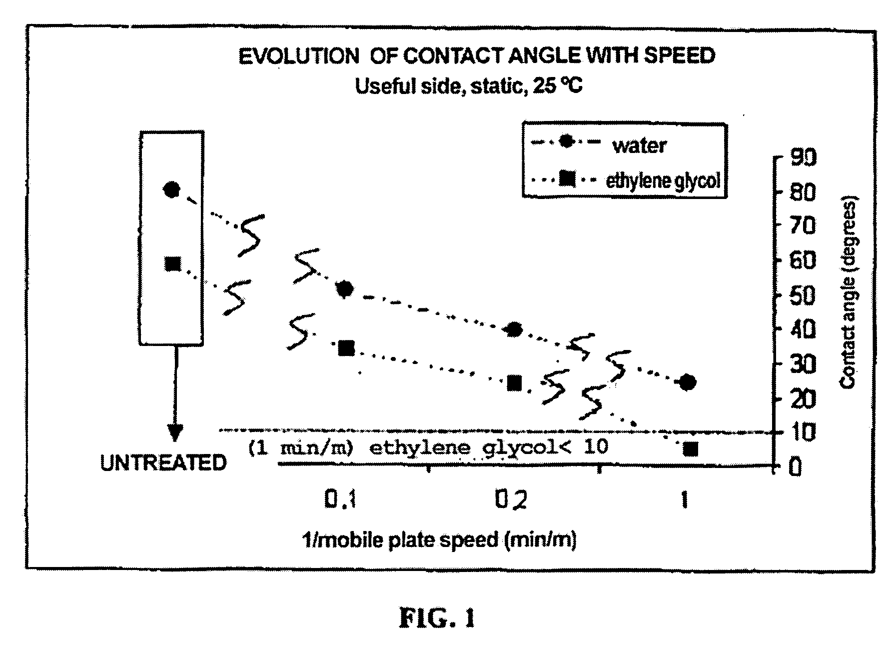
[0040] The use of the method object of the present invention has proven effective in the activation of polymeric substrates, increasing their surface energy and wettability. Said surface activation is greatly important when it comes to increasing the mechanical properties of adhesive bonds between members manufactured with polymeric matrix composite materials reinforced with carbon fiber. At present, a large number of aeronautical structures are manufactured by means of the adhesive bonding of components manufactured with composite materials of these characteristics, so the use of the method object of the present invention improves the general performance of these structures.
[0041] The method object of the present invention improves the adhesion of the treated polymeric substrates, as it generates superficially oxygenated active species, modifies the topography, and reduces the presence of contaminants such as fluorine or silicones, which are highly detrimental to adhesive bond efficiency. Thus, not only does it not require prior or subseque
Problems solved by technology
This is due to the fact that the mechanical stress applied on the adhesive bond causes a substantial local distortion of the phases, and in case the materials are dissipative materials, a considerable consumption of energy occurs in the regions close to the failure due to the viscoelastic or plastic deformations.
Polymeric surfaces are usually difficult to wet and bond due to the fact that they have low levels of surface energy, they may be incompatible with the adhesives or even chemically inert, or simply be coated with weak boundary layers or contaminants.
The number of factors involved in the final efficiency of adhesive bonds between polymeric materials makes it very difficult to find systems of assuring their quality.
The intervention of so many variables in the adhesion phenomenon in some cases makes achieving stability and repeatability in the result obtained in an adhesive bond complicated.
This is why on many occasions the control of bonded joints requires complex and expensive tests that are used to assure the final quality.
All these treatments are widely developed in innumerable industrial applications, but many of them have certain drawbacks: Chemical Methods: the use of organic solvents such as methyl-ethyl ketone (MEK), isopropyl alcohol (IPA), acetone or toluene in cleaning and surface preparation processes presents risks of inflammability as well as safety and hygiene problems for operators.
Furthermore, in the event that the abrasion is excessive, the topography of the treated surface may be seriously damaged, reducing the contact surface, affecting the mechanical cross-linking, and in short weakening the adhesive bond.
All these methods are wide spread in the polymer processing industry, but their main drawback lays in the lack of stability of the treated surfaces.
Another drawback of this type of treatments is that they cause molecular division processes.
The splitting gives rise to low molecular weight surface species generating new interfaces that m
Method used
View moreImage
Smart ImageViewing Examples
Examples
 PUM
| Property | Measurement | Unit |
|---|---|---|
| Length | aaaaa | aaaaa |
| Length | aaaaa | aaaaa |
| Angle | aaaaa | aaaaa |
Abstract
The invention relates to a method of surface treatment of predetermined areas of a composite material structure with at least one plasma beam at atmospheric pressure, produced by a plasma generator provided with an emission nozzle in order to facilitate its adhesive bonding to another structure, in which: a) the plasma beam emitted through the nozzle may include a reactive gas, is projected on the composite material structure from a distance comprised between 0,2 and 10 cm; b) the plasma beam is projected on the composite material structure with an angle of incidence comprised between 75° and 105°. It is preferably applied to carbon fiber or fiberglass and epoxy resin or bismaleimide resin structures. Other relevant variables in the process are the plasma beam power and the treatment rate.
Description
FIELD OF THE INVENTION [0001] The invention relates to a method of surface treatment of composite surfaces with atmospheric plasma beams, particularly to facilitate their adhesive bonding to another composite material surface or another substrate. BACKGROUND OF THE INVENTION [0002] The design of adhesive bonds is currently a field of growing interest within the aeronautical industry, especially in the case of structures manufactured with carbon fiber composite materials. The number and structural importance of adhesive bonds progressively grow over the years, and in most cases, the strength of the structures is determined by the strength of their bonds. [0003] Adhesive bonds have numerous advantages with respect to traditional mechanical bonds (riveted or screwed): these bonds do not require drilling of the structure, they distribute the stresses over a greater area than mechanical bonds, and add less weight and have greater strength to fatigue. [0004] The result obtained upon carry...
Claims
Login to View More Application Information
Patent Timeline
 IPC IPC(8): B08B6/00
CPCB29C59/14B29C2059/145C08J7/123C08J2363/00C09J5/02C09J2400/146C09J2463/008C09J2479/088
Inventor URENA, SILVIA LAZCANO
Owner AIRBUS OPERATIONS SL
Features
- R&D
- Intellectual Property
- Life Sciences
- Materials
- Tech Scout
- Unparalleled Data Quality
- Higher Quality Content
- 60% Fewer Hallucinations
Learn More Browse by: Latest US Patents, China's latest patents, Technical Efficacy Thesaurus, Application Domain, Technology Topic, Popular Technical Reports.
© 2025 PatSnap. All rights reserved.Legal|Privacy policy|Modern Slavery Act Transparency Statement|Sitemap|About US| Contact US: help@patsnap.com


