Electrical Connector Assembly
- Summary
- Abstract
- Description
- Claims
- Application Information
AI Technical Summary
Benefits of technology
Problems solved by technology
Method used
Image
Examples
Embodiment Construction
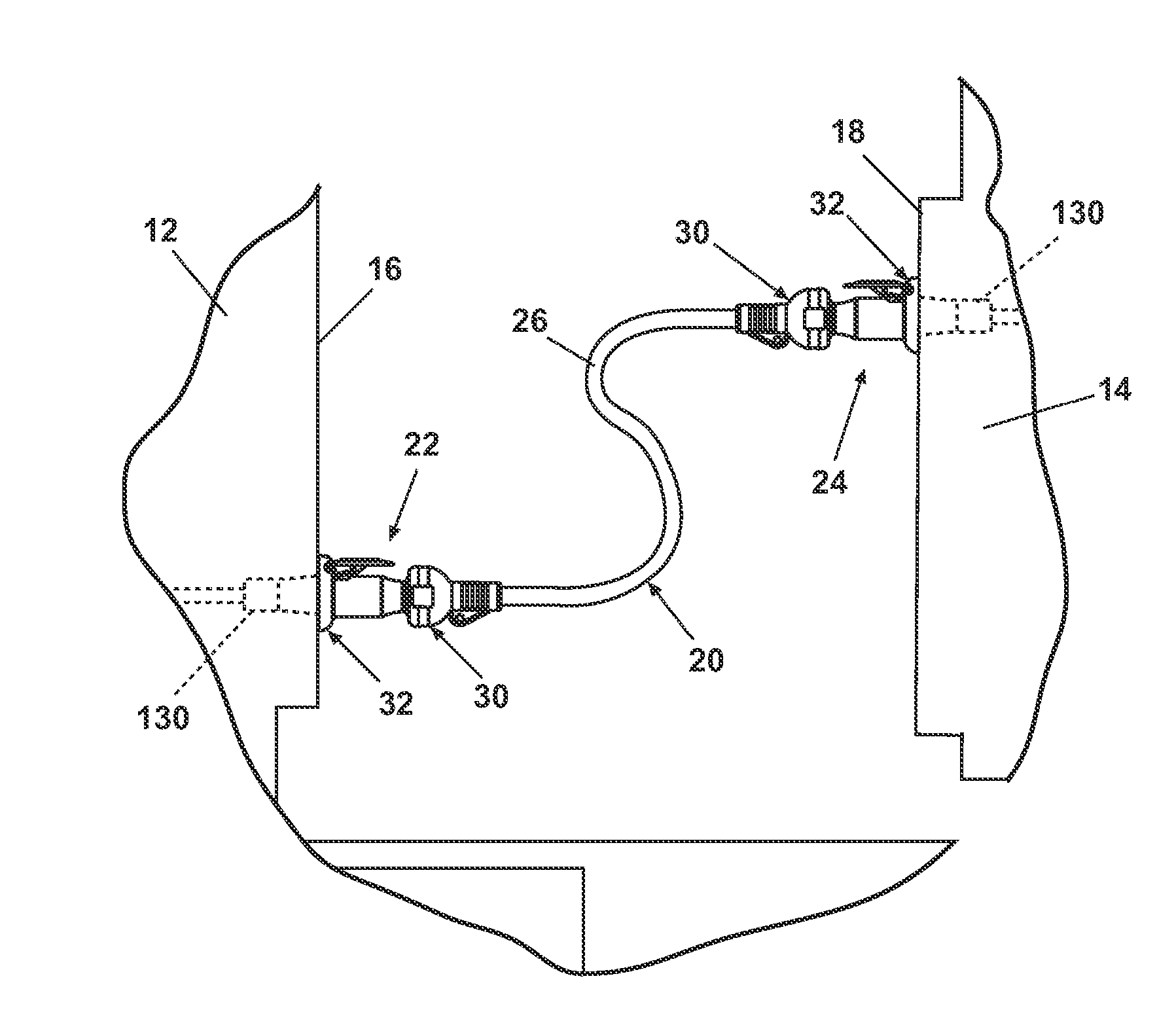
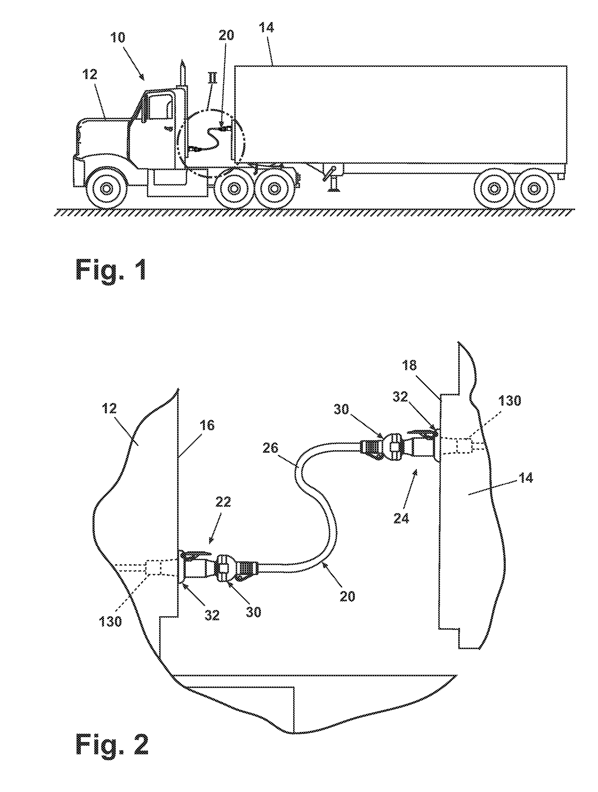
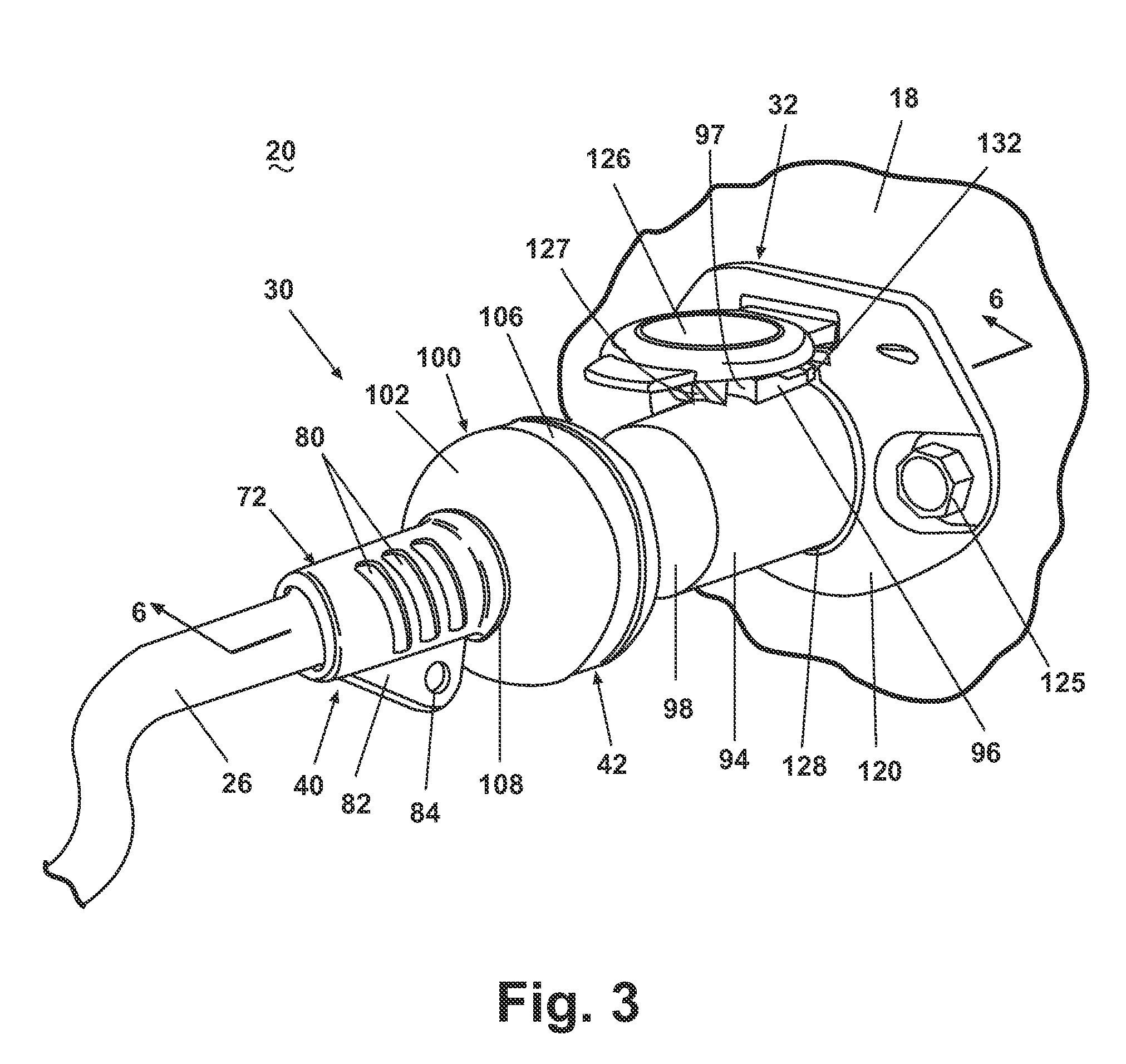
[0031] Referring now to the figures, FIG. 1 illustrates an exemplary, conventional tractor-trailer 10 comprising a tractor 12 electrically coupled to a trailer 14 by an electrical connector assembly 20 according to one embodiment of the invention. As shown in FIG. 2, which is an enlarged view of the area labeled II in FIG. 1, the tractor 12 includes a rear wall 16 that supports a tractor portion 22 of the electrical connector assembly 20, and, similarly, the trailer 14 has a front wall 18 that supports a trailer portion 24 of the electrical connector assembly 20. The tractor portion 22 and the trailer portion 24 are connected by a cable 26 of sheathed electrical wires to electrically couple the tractor 12 to the trailer 14. The cable 26 terminates at a pair of plugs 30, which are removably received by a corresponding socket 32 mounted to the corresponding rear wall 16 of the tractor 12 or the front wall 18 of the trailer 14. While the electrical connector assembly 20 is shown and de...
PUM
 Abstract
Description
Claims
Application Information
 - R&D
- Intellectual Property
- Life Sciences
- Materials
- Tech Scout
- Unparalleled Data Quality
- Higher Quality Content
- 60% Fewer Hallucinations
Browse by: Latest US Patents, China's latest patents, Technical Efficacy Thesaurus, Application Domain, Technology Topic, Popular Technical Reports.
© 2025 PatSnap. All rights reserved.Legal|Privacy policy|Modern Slavery Act Transparency Statement|Sitemap|About US| Contact US: help@patsnap.com


