Image heating apparatus
a heating apparatus and image technology, applied in the field of image heating apparatus, can solve the problems of decreasing the heating efficiency of the belt, reducing the amount of heat generation around the metal member, and non-uniform temperature, and achieve the effect of reducing the heating efficiency attributable to the inside metal member
- Summary
- Abstract
- Description
- Claims
- Application Information
AI Technical Summary
Benefits of technology
Problems solved by technology
Method used
Image
Examples
embodiment 1
(1) Example of Image Forming Apparatus
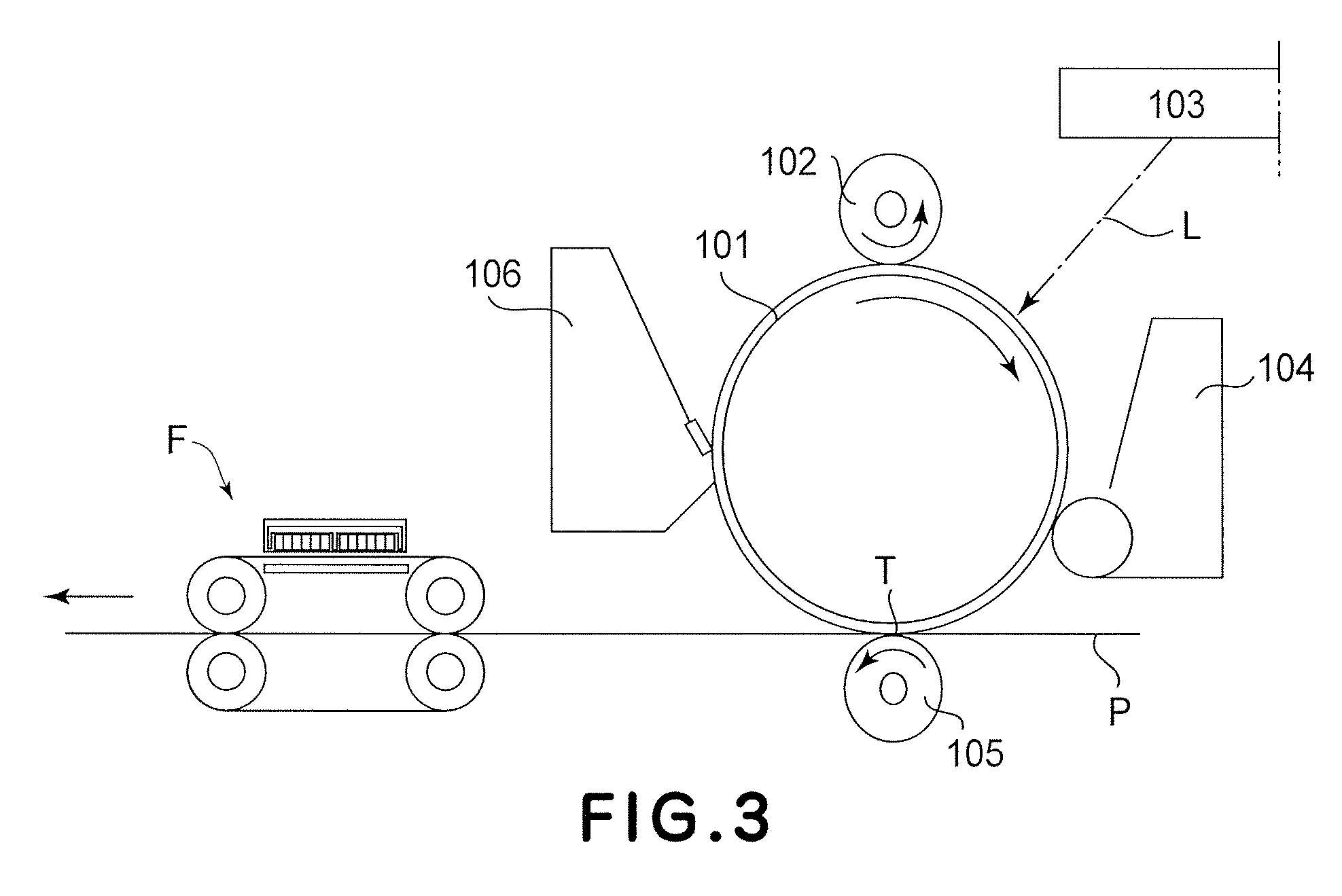
[0023]FIG. 3 is a schematic drawing of an image forming apparatus in which an image heating apparatus in accordance with the present invention is mountable as a fixing apparatus, showing the general structure thereof. This image forming apparatus is a laser beam printer which uses an electrophotographic image formation process.
[0024] Designated by a referential symbol 101 is a photosensitive drum as an image bearing member. The photosensitive drum 101 is made up of a cylindrical substrate formed of aluminum, nickel, or the like, and a layer of photosensitive substance, such as OPC, amorphous Selenium, or amorphous Silicon, coated on the peripheral surface of the cylindrical substrate. The photosensitive drum 101 is rotationally driven in the clockwise direction indicated by an arrow mark. As the photosensitive drum 101 is rotated, first, its peripheral surface is uniformly charged by a charge roller 102 as a charging apparatus. Next, the unif...
embodiment 2
[0046]FIG. 4 is a schematic vertical cross-sectional view of the fixing apparatus in this embodiment.
[0047] The members and portions of this fixing apparatus, which are the same as those of the fixing apparatus in the first embodiment, are given the same referential symbols as those given to describe the first embodiment, and will not be described here. This arrangement regarding the referential symbols also applied to the third to fifth embodiments.
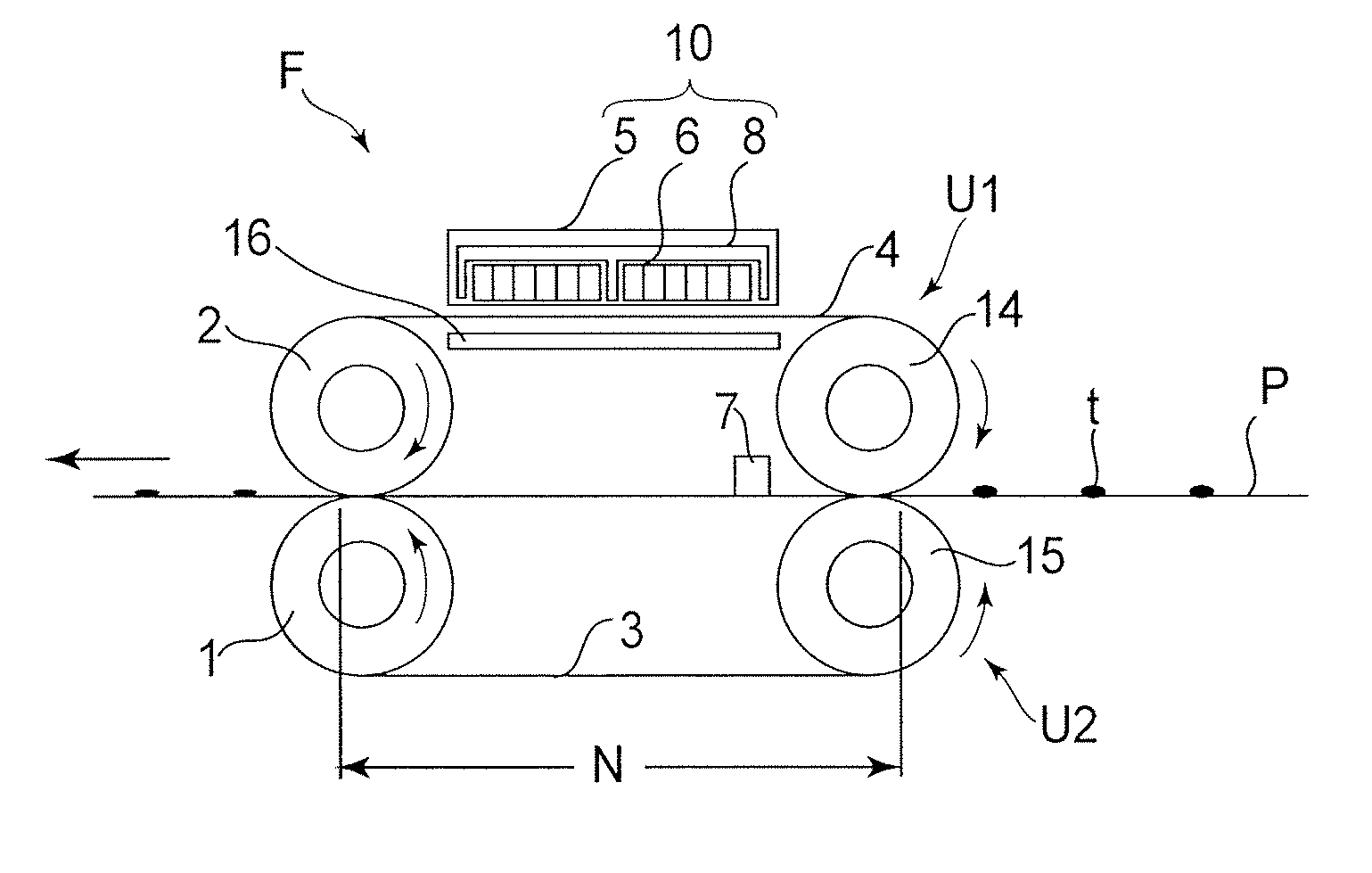
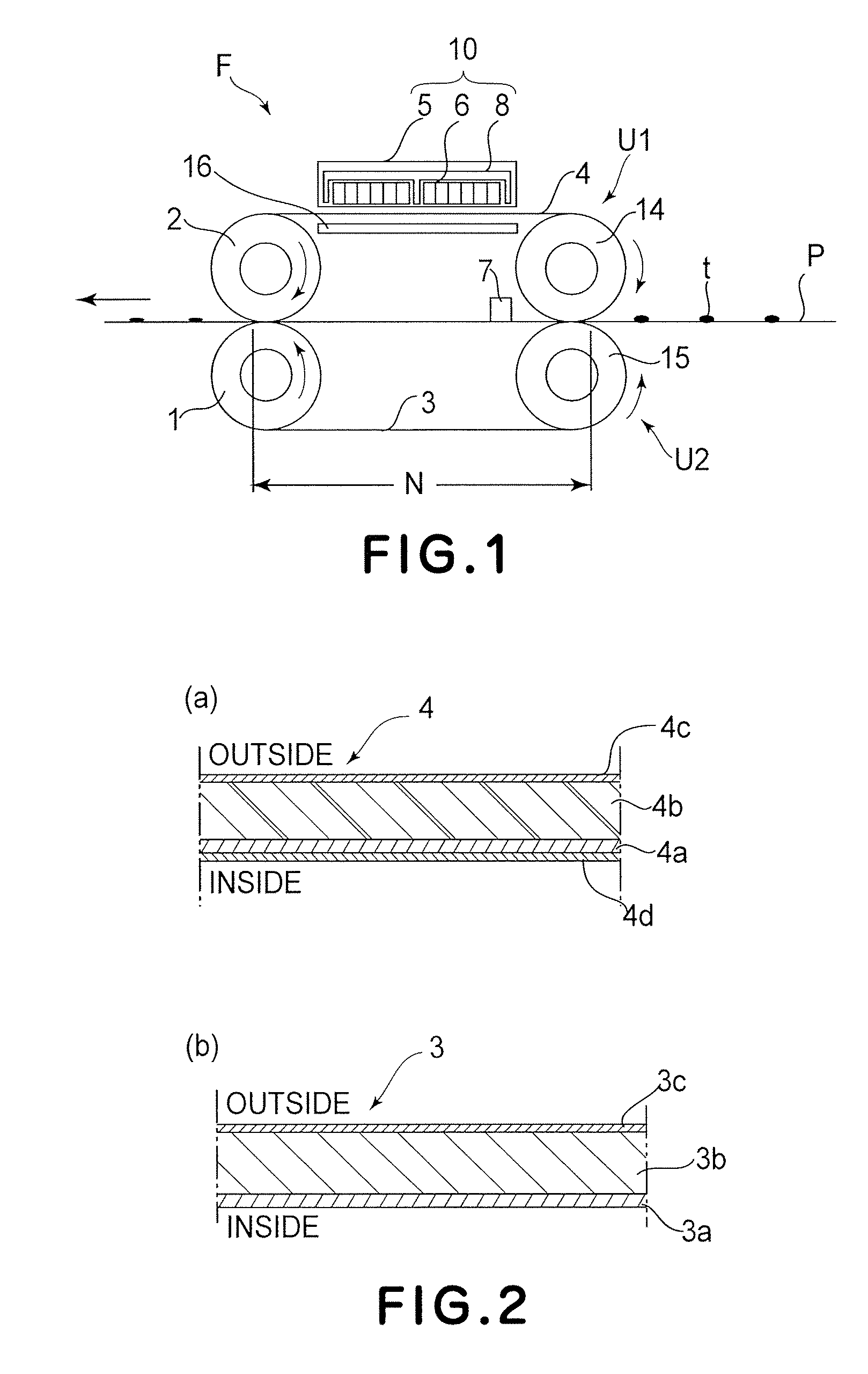
[0048] The fixing apparatus F in this embodiment has a stay 17, which is disposed on the inward side of the fixation belt loop, and to which the components to be disposed on the inward side of the fixation belt loop are attached. The stay 17 is supported at this lengthwise ends by the pair of lateral plates of the fixing apparatus F. To the bottom surface of this stay 17, that is, the surface of the stay 17, which is on the nip side, a fixation pad 19 is attached. The fixation belt 4 and pressure belt 3 are pinched by this fixation pad...
embodiment 3
[0055]FIG. 6 is a schematic vertical cross-sectional view of one of the fixing apparatus in this embodiment. FIG. 7 is a schematic vertical cross-sectional view of the other of the fixing apparatus in this embodiment.
[0056] The fixing apparatus F in this embodiment has the modified version of the heat concentration member 16 in the second embodiment; the heat concentration member 16 in the second embodiment has been devised in shape to be rendered more rigid.
[0057] The length of the heat concentration member 16 is the same as the dimension of the fixation belt 4 in the lengthwise direction. Therefore, it is possible that the heat concentration member 16 will warp or bend across its center portion in terms of the lengthwise direction. It is also possible that the heat concentration member 16 will be difficult to handle when assembling the fixing apparatus F.
[0058] In this embodiment, therefore, the heat concentration member 16 is formed as an integral part of the stay 17, preventi...
PUM
 Abstract
Description
Claims
Application Information
 - R&D
- Intellectual Property
- Life Sciences
- Materials
- Tech Scout
- Unparalleled Data Quality
- Higher Quality Content
- 60% Fewer Hallucinations
Browse by: Latest US Patents, China's latest patents, Technical Efficacy Thesaurus, Application Domain, Technology Topic, Popular Technical Reports.
© 2025 PatSnap. All rights reserved.Legal|Privacy policy|Modern Slavery Act Transparency Statement|Sitemap|About US| Contact US: help@patsnap.com


