
Inverted portal axle configuration for a low floor vehicle

a low-floor vehicle and inverted technology, applied in mechanical equipment, transportation and packaging, gearing, etc., can solve the problems of difficult packaging and difficult to achieve large distances, and achieve the effect of low flow profil

Inactive Publication Date: 2007-03-29
ARVINMERITOR TECH
View PDF11 Cites 8 Cited by
  • Summary
  • Abstract
  • Description
  • Claims
  • Application Information

AI Technical Summary

Benefits of technology

[0008] Disc brakes are integrated in the inverted portal axle system and are typically air operated by a pneumatic cylinder. The pneumatic cylinders are mounted to define a cylinder axis from a generally vertical orientation. The rotated axis allows for a more compact packaging of the brake actuator and suspension rod brackets.
[0009] The present invention therefore provides an inverted portal axle configuration which provides for an ultra low flow profile while minimizing the ramp angle on the vehicle floor over the drive axle.

Problems solved by technology

Larger distances may be difficult to achieve due to the very large size of the idler gears, which would be expensive and difficult to package properly, due to wheel, brake, and suspension constraints.
Slopes in the range of 8 to 12 degrees are typical but are considered excessive; therefore, a larger axle beam drop is desired.

Method used


Image

  • Inverted portal axle configuration for a low floor vehicle
  • Inverted portal axle configuration for a low floor vehicle
  • Inverted portal axle configuration for a low floor vehicle

Examples


Embodiment Construction

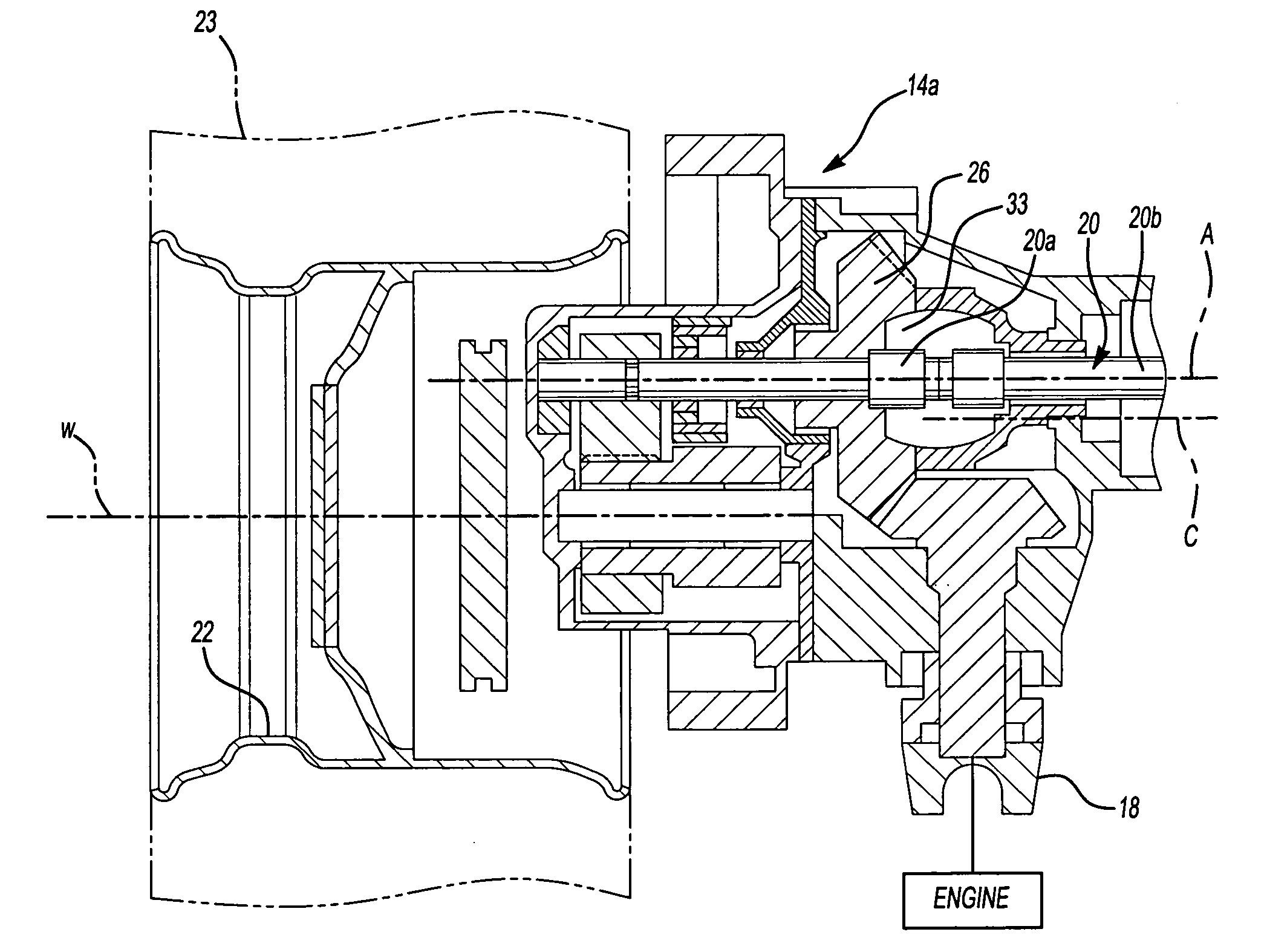
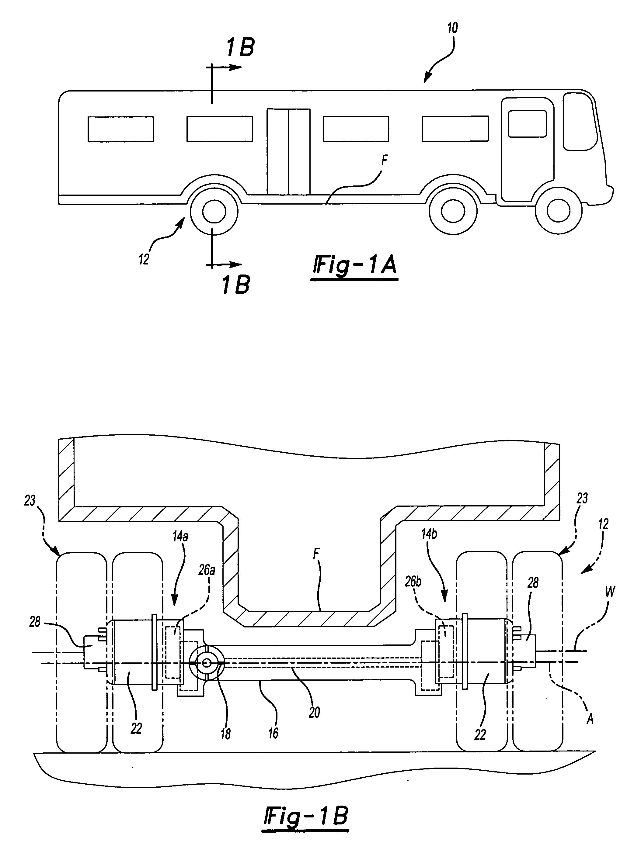
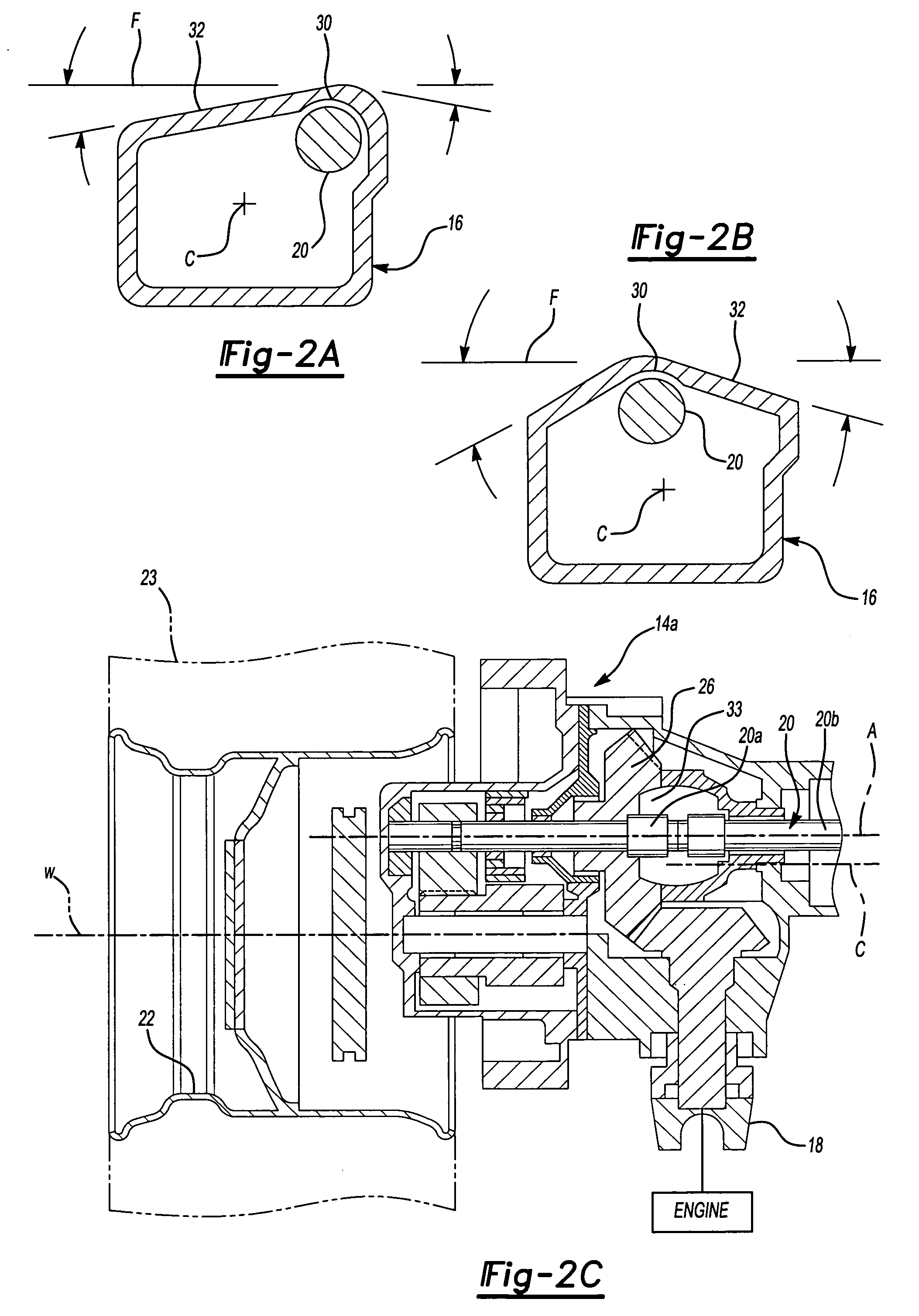
[0018]FIGS. 1A and 1B schematically illustrate a vehicle 10 incorporating an inverted portal axle system 12 adjacent a vehicle floor F. The inverted portal axle 12 includes a pair of side reduction gear system housings 14A, 14B interconnected by an axle center beam housing 16. An input 18 is positioned near one of the side reduction gear system housings 14A, 14B and a shaft assembly 20 connects the input 18 to the other side reduction gear system housings 14A, 14B. It should be understood that the shaft assembly 20 may include one or more axle segments. The shaft 20 defines an axle axis of rotation A.

[0019] Each side reduction gear system housing 14A, 14B includes a wheel hub assembly 22 driven by a gear reducer (illustrated schematically at 26A, 26B) which is preferably a double stage reduction gearbox providing the required speed reduction. The gear reduction 26A, 26B drives a spindle 28 (also illustrated in FIG. 2C), which drives the wheel hub assembly 22 and tires 23. The gear ...


PUM


Abstract

An axle system includes an axle shaft offset located within an axle center beam housing. The axle shaft is located in a recess in a top wall of the axle center beam shaped with slopes to maximize clearance to the bottom of the vehicle floor panels. The pneumatic brake cylinders define a cylinder axis angled within an angular range from a generally vertical orientation for enhanced packaging.

Description

BACKGROUND OF THE INVENTION [0001] The present invention relates to an inverted portal axle configuration which provides for a vehicle having a low floor. [0002] Mass transit vehicles, such as trolley cars, buses, and the like typically have seats aligned at the lateral sides of the vehicle, with a central aisle and floor extending along the vehicle. In order to facilitate entering and exiting from the vehicle, it is desirable to have the vehicle floor and aisle positioned relatively low to the ground. This provides faster cycle time at bus stops. [0003] Many such vehicles provide a rigid axle having a gear box at each longitudinal end to form an inverted portal axle configuration. The inverted portal axle configuration is particularly effective in providing a low floor vehicle. [0004] In the inverted portal axles, the axle shafts are offset vertically relative to the wheel axis by a specific distance, the so-called axle shaft drop. That is, the axle shaft drop is the offset between...

Claims


Application Information

Patent Timeline
IPC IPC(8): B60K17/00B60B35/16
CPCB60B11/02B60B35/002B60Y2200/1432B60B35/163B60B35/122Y10S180/905
Inventor BRILL, LAWRENCE D.CONTI, CORRADO A.HAYES, BRIAN D.HUNTER, STEVEN E.MAINERI, FABIOVARELA, TOMAZ DOPICO
Owner ARVINMERITOR TECH
Learn More