
Body mounted weapons platform

a technology of weapons platform and body, which is applied in the field of improved platforms, can solve the problems of low visibility, unsteady users, and inability of firearm users to efficiently find their targets, and achieve the effect of better optical reconnaissance and better visibility

Inactive Publication Date: 2007-03-29
ENDRES STEVEN J
View PDF29 Cites 1 Cited by
  • Summary
  • Abstract
  • Description
  • Claims
  • Application Information

AI Technical Summary

Benefits of technology

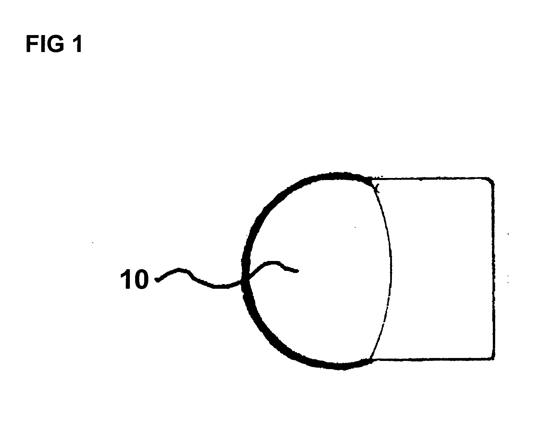
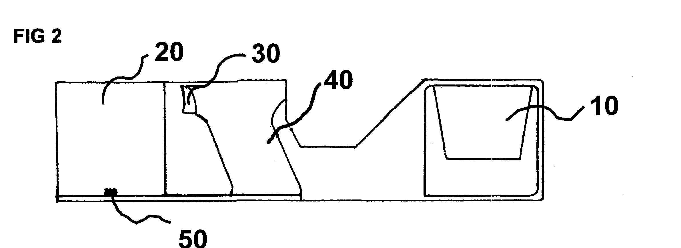
[0012] This invention discloses a Body Mounted Weapons Platform (hereinafter “BMWP”), which is a device that attaches to the right (or left, depending on the user's inclination) forearm, and allows the user to mount within it one or two firearms and two cameras. The device itself is designed such that it provides the user support as he is operating the firearm, while the device stays on the user's arm via a hook-look-type fastener. Furthermore, the cameras are designed such that they provide the user better optical reconnaissance. The BMWP is designed to utilize cameras that have the capability of seeing in light or dark, and through weather conditions such as rain, smoke or fog. Furthermore, they allow individuals who do not trust their eyes (because of vision problems) to have better visibility while operating their firearm. The cameras also provide the user a full field of view with out exposing oneself because of the fact that they will be able to see through the cameras without having to target in the traditional “stand in front of the target” fashion.

Problems solved by technology

During times of smoke, rain, fog, and darkness, visibility is low, and firearms users cannot efficiently find their target.
Users can become unsteady, and because there is no safety net for most weapons if the weapons slip out of a user's hands, not only can the weapons fall into the wrong hands, but they could potentially cause harm if misfired.
Most firearms are not affixed to anything, and because human nature warrants that an individual could potentially lose their balance or grip, the firearm may cause safety concerns.
Particularly in the instance of the military and law enforcement, oftentimes they cannot afford to stand up, face their target, aim, and shoot.
Users do not have a way of targeting without getting into a stance, and because of that, firearms can in turn be inefficient.
Relevant art has attempted to address some (but not all) of these problems, however has not directly addressed all of these concerns.
Iannetta's device, however, does not address any of the concerns relating to limited visibility, target cognizance, and even the safety of the user and others.
Although it presents the idea of a mounted firearm, it simply mounts it on another firearm, which could potentially cause the same problems as if it was not mounted on anything.
Holmberg's invention, however, does not address the safety concerns associated with firearms that have no safety net.
Furthermore, Holmberg's device does not provide a means by which an individual can improve visibility while advancing their targeting abilities.
Matsumoto's invention, however, magnifies the concern regarding safety because this weapon is rather light, and therefore can easily slip out of the user's hands.
Furthermore, Holmberg's invention does not disclose that the lens in any way can aid during times of limited visibility.
Although prior art attempts to somewhat solve some of these problems, prior art does not come close to providing a device that quenches all of the concerns regarding firearms and users.

Method used


Image

  • Body mounted weapons platform
  • Body mounted weapons platform
  • Body mounted weapons platform

Examples


first embodiment

[0040] The first embodiment allows the user to mount within it one firearm, and the firearm can be removed and replaced with different firearms for different operations, depending on the requirements of the user. The firearm may be inserted as directed above, and requires bolting of 4 screws (120) to hold down the barrel (70), as shown in FIG. 10. The mounting plate (90) for each firearm can enter the stock. The mounting plate (90) holds the apparatus in alignment, in order to keep the device tight on the user's arm so that it is not falling off. Furthermore, the mounting plate (90) should be able to easily slip in and out in order to replace the weapons mounted in the platform. At the rear of the mounting plate (90) is wiring (130) that goes through the bracket and splits into two electrical connections (140), finally connecting inside the stock (110), as shown in FIG. 11. This powers the firearm, in conjunction with the 9V battery (80), such that the solenoid is powered, allowing ...

second embodiment

[0042] The second embodiment incorporates both lethal (150) and non-lethal (160) firearms. In addition to the two camera cutouts described earlier, this model contains cutouts for the installation of lights (170) and tazers (180). The tazers (180), cutout for lethal (150), and nonlethal (160) weapons allow the user many options for dealing with any combat situation (FIG. 12). The cutout for the installation of a flashlight is preferred as a 4×4—inch cutout. The cutout for the lights (170) serves to allow optimal recognizance in the dark, or through bad weather. The cutout for the tazer is preferred as a half circle cutout with a 1-inch diameter. There are two cutouts for the placement of firearms into the SE18L: The top cutout (150) is a circular cutout with a 785 / 1000th - inch diameter, and is designed for a lethal weapon, such as a 44-caliber automatic weapon or any other lethal weapon based on the requirements of the user. The bottom cutout (160) is a circular cutout with a 875 / 1...


PUM


Abstract

A body mounted weapons platform is disclosed that attaches to a user's forearm and allows the user to mount within it one or two firearms (depending on the user's preferred embodiment) and two cameras. Both embodiments of the body mounted weapons platform will help improve optical reconnaissance, firearm safety, and targeting skills.

Description

[0001] A body mounted weapons platform is disclosed that attaches to a user's forearm and allows the user to mount within it one or two firearms (depending on the user's preferred embodiment) and two cameras. Both embodiments of the body mounted weapons platform will help improve optical reconnaissance, firearm safety, and targeting skills. U.S. patents6,032,397Mar. 7, 2000Iannetta6,556,245Apr. 29, 2003HolmbergJapanese Patent Publication58022448Feb. 14, 1983MatsumotoDISCUSSION BACKGROUND OF THE INVENTION [0002] 1. Field of the Invention [0003] This invention pertains to an improved platform to which weapons could be mounted, and is specifically directed to a device designed for mounting a firearm and two cameras (for improved targeting) to the forearm. [0004] 2. Discussion of Related Art [0005] Military and law enforcement officers use firearms on a daily basis; however there are many concerns with the current method of firearms use. The first concern is that oftentimes conditions ...

Claims


Application Information

Patent Timeline
IPC IPC(8): F41A23/00
CPCF41A23/02F41G3/165F41G1/387F41G1/32F41C33/001
Inventor ENDRES, STEVEN J.
Owner ENDRES STEVEN J
Learn More