Design of a signal switch

Inactive Publication Date: 2007-03-22
ALCOR MICRO CORP
View PDF1 Cites 5 Cited by
  • Summary
  • Abstract
  • Description
  • Claims
  • Application Information

AI Technical Summary

Benefits of technology

[0008] It is an object of the present invention to provide an improved signal switch utilizing, at least, one combinational logic, such as one or more chips, and a multiplexer, suitable for sharing a plurality of hosts. The present invention provides a design that is contrary to those prior art's designs of utilizing the CPU within the conventional signal switches. The present invention utilizes different types of chips and multiplexer in an improved signal switch in order to detect and interpret signals so that the connections between the plurality of hosts and an input control device can be controlled or altered. The multiplexer of the switch system of the present invention is connected to the plurality of hosts and the input controlling device, wherein the ICs of the multiplexer can determine which one of the hosts is currently connected to the multiplexer. It is another object of the present invention to provide an improved design of the signal switch that can reduce the enumerating time and no specific device driver software is required to install to operate the signal switch. The improved signal switch comprises a first chip, a plurality of hosts and at least one set of keyboard and mouse. The first chip further comprises a plurality of second chips and a plurality of hubs and a multiplexer. The multiplexer of the present invention is utilized to detect and interpret signals. The present invention utilizes the design of the chips and the multiplexer to provide a signal switch that can share multi-upstream devices but less downstream ports, only one set of keyboard and mouse is required. By having a dedicated hub connected to each upstream host would require less enumeration time, which comprise the configuration of a hub and its descendant devices. The signal switch of the present invention provides an improved design by replacing the central processing units (CPU) of a conventional design of signal switch with the chips 100&111′-114 in order to increase the speed of the enumeration, as a result, the enumerating time is thus reduced. Since there is no CPU installed in the signal switch of the present invention, therefore, no need to install a device driver and / or firmware under specific software in order to operate the switching system.

Problems solved by technology

With the increasing demands of computer applications in various areas, the utility and usefulness of computers increase, and integrated circuit (IC) connections become more complex.
If any signal input device that is incompatible with the FM of the CPU, either the FM of the embedded CPU needs to be altered or the type of the input device needs to be changed, it is clearly obvious inconvenience to the user.
Therefore, the compatibility of the conventional signal switch such as the one shown in FIG. 1 is very low as it is restricted to certain types of signal input device.
Furthermore, those conventional signal switches that require specific firmware to be installed in the embedded CPU in order to operate its driver of the signal switches induce another problem: its reliability.
Once particular software is installed in the CPU, different type of signal input devices, may not be compatible to interact with the CPU fairly well.
In other words, the signal switch may still functions but performs poorly due to its poor compatibility.
The reliability of the conventional signal switch is then reduced drastically due to its subjection to certain limitations.
Therefore it induces inconvenience for the users to restrict to certain types of input control devices that can be connected to the signal switch.
Furthermore, those current conventional signal switches utilize the CPU to detect and convert the signals, the enumeration process of the system would require longer time to abstract or detect signals of the devices.

Method used


Image

  • Design of a signal switch
  • Design of a signal switch
  • Design of a signal switch

Examples


Embodiment Construction

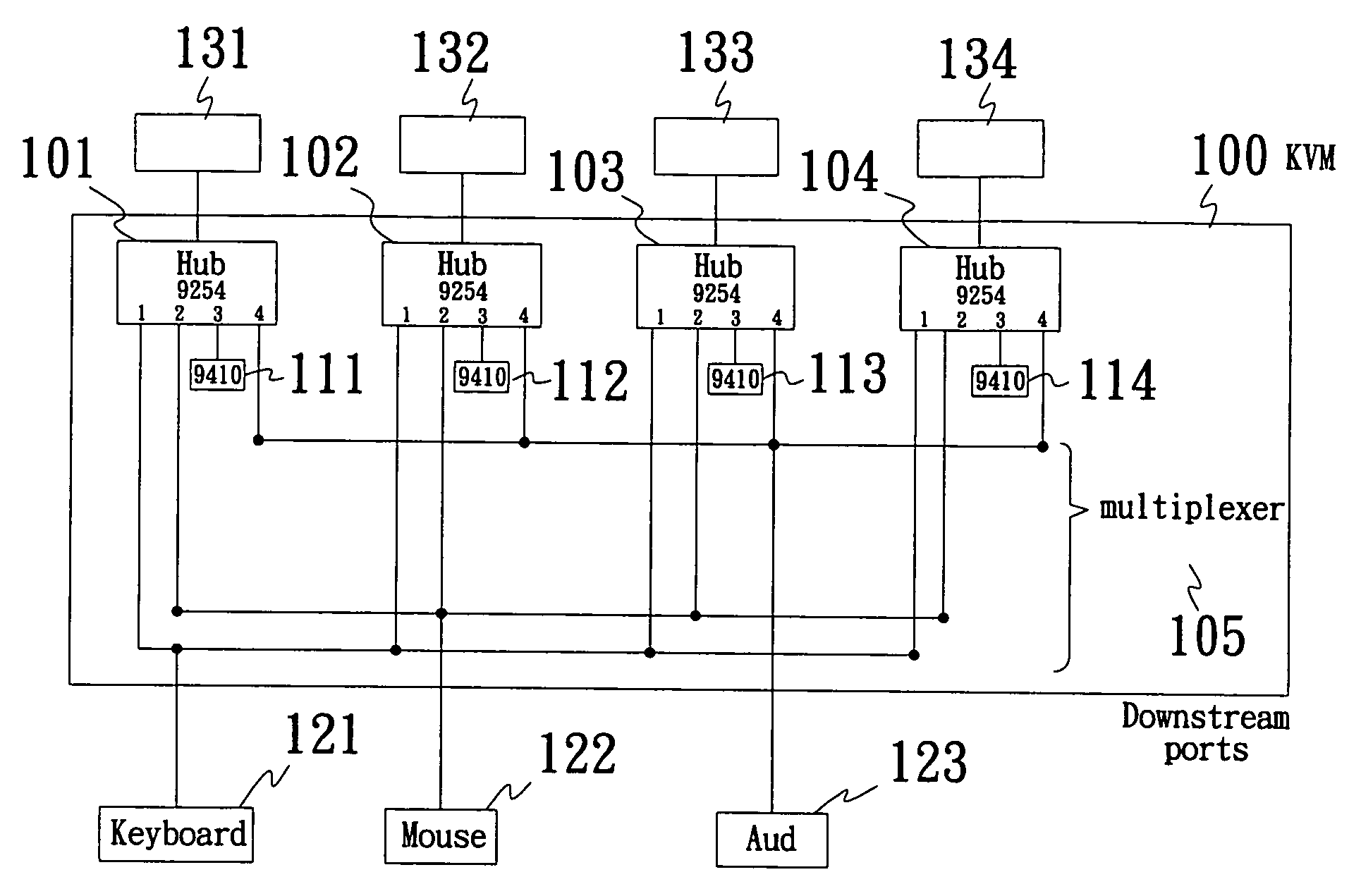
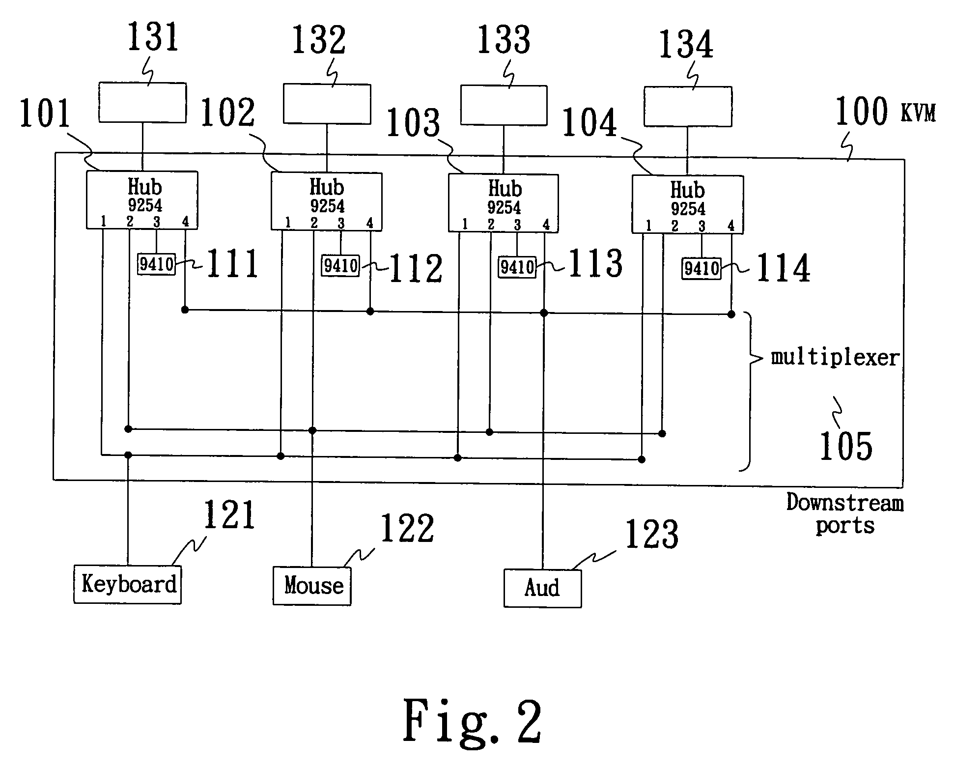
[0013] The present invention provides an improved design of a signal switch, suitable for sharing a plurality of hosts and at least one set of keyboard, mouse and video. Refer to FIG. 2, a signal switch 10 utilizing at least one combinational logic such as a first chip 100 to sending and receiving signals, suitable for sharing a plurality of hosts 111-114. However, the design / objects of the present invention is / are not limited to utilization of chips or restricted to the number of chips mentioned in this embodiment. The improved signal switch of the present invention comprises at least one combinational logic, wherein each combinational logic further comprises a first chip 100, a plurality of second chips 111-114. A set of input controlling device can be such as, a keyboard 121, a mouse 122 is connected to each combinational logic, in addition to an output device, such as a video 123. The first chip 100 further comprises a plurality of hubs 101-104 and a multiplexer 105. One end of ...


PUM


Abstract

The present invention provides an improved design of the signal switch, wherein the signal switch comprises at least one combinational logic such as a chip, a plurality of hosts and at least one set of input control device such as a keyboard and a mouse. The chip can further comprise one or more virtual keyboard controller and a plurality of hubs and a multiplexer. The multiplexer of the present invention is utilized to detect and interpret signals. The present invention utilizes the combinational logic design of the chips and the multiplexer to provide a signal switch that can share multi-upstream devices but less downstream ports, only one set of keyboard and mouse is required. Multiplexing downstream devices among multiple hubs, which are dedicated to upstream hosts, help reducing the whole enumeration process of time. The signal switch of the present invention provides an improved design by replacing the central processing units (CPU) of a conventional design of signal switch with the combinational logics such as chips in order to increase the speed of the enumeration, as a result, the enumerating time is thus reduced.

Description

BACKGROUND OF THE INVENTION [0001] 1. Field of Invention [0002] The present invention relates generally to a signal switch system utilizing various chips and a multiplexer. More particularly, the present invention relates to an improving design of a signal switch that is software driver-free and its enumerating time is reduced. [0003] 2. Description of the Related Art [0004] Present-day society increasingly relies on computers, computer systems, computer software applications and computer devices as computers become more essential in everyday life. With the increasing demands of computer applications in various areas, the utility and usefulness of computers increase, and integrated circuit (IC) connections become more complex. Various techniques have been developed to increase computer devices connections while providing a more compact computer with high performance. [0005] Devices such as various signal switches are used to share a plurality of output devices, such as computer host...

Claims


Application Information

Patent Timeline
IPC IPC(8): G06F13/00
CPCG06F13/4072
Inventor CHANG, CHI-TUNG
Owner ALCOR MICRO CORP
Why Eureka
Try Eureka