
Method and apparatus for dynamic image contrast expansion

a dynamic image and contrast technology, applied in image enhancement, color signal processing circuits, instruments, etc., can solve the problems of loss of image gray level distribution range in an actual video transmission, deterioration of video quality, attenuation of video contrast, etc., to effectively reduce the noise produced, the effect of eliminating flickering

Inactive Publication Date: 2007-03-22
MARKETECH INT
View PDF1 Cites 29 Cited by
  • Summary
  • Abstract
  • Description
  • Claims
  • Application Information

AI Technical Summary

Benefits of technology

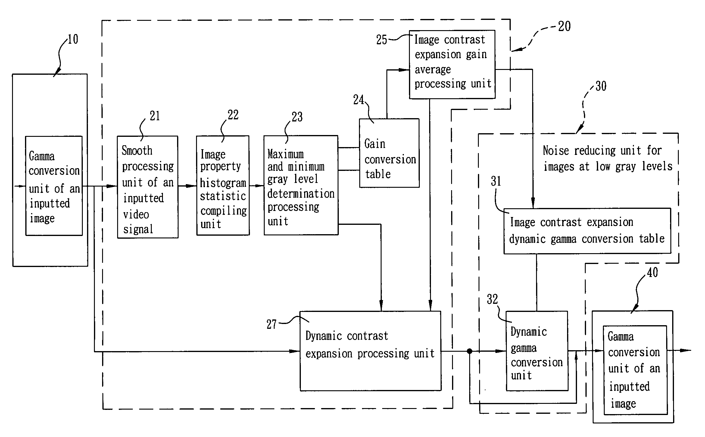
"The present invention provides a novel dynamic image contrast expansion technique for dynamically expanding the image contrast to an optimal value according to the image gray level distribution range, to eliminate flickering and reduce noises during a dynamic change of screens. The method includes performing a gamma conversion for the inputted image to convert the relationship of brightness and gray level of the image into a linear relation, performing a subtraction for the gray level value of the image to maintain its smallest color deviation, analyzing the image property histogram to compute the maximum and minimum gray levels required for carrying out the image contrast expansion, and using an average of several previously inputted image contrast expansion gains and a current image contrast expansion gain as the contrast expansion gain to compute a new outputted gray level value after the image contrast expansion is performed. The invention also avoids the flickering and reduces the noises in the image by using a minimum gray level for the formula of computing the dynamic contrast expansion, and a preset gain conversion table to look up the image contrast expansion gain according to the maximum and minimum gray levels. Additionally, the invention converts the relation of brightness and gray level of the outputted image so that the product of the gamma value of the outputted image and the gamma value of a video display is maintained at 1.0 according to the optoelectronic properties of the video display and the gamma value of the video display module corresponding to the brightness and gray level."

Problems solved by technology

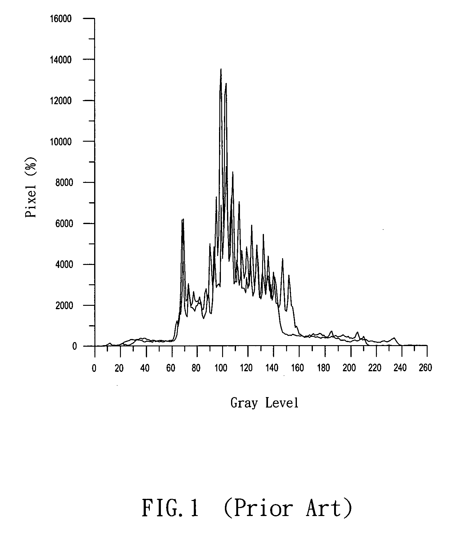
For example, an 8-bit 256 gray-level image has a maximum gray level range of 0˜255, but there is a loss of the image gray level distribution range in an actual video transmission due to the signal attenuation of photography, duplication and transmission.
In a general 8-bit television video system, the actual number of gray levels of the video display is less than 256, and thus the video contrast will be attenuated, and the video quality will be deteriorated.
In addition to the foregoing factors, the properties and parameters of the analog components in the video interface also cause a loss of the image gray level distribution range and adversely affect the displaying effect.
Since a plasma display panel (PDP) usually comes with a large screen and its structural properties are totally different from those of traditional color cathode ray tubes (CRT), therefore the dynamic contrast expansion technique used for the traditional small-size CRT televisions cannot be used directly for the plasma display panels.
The most difficult point is to avoid the flickering of a large plasma display panel, the too-low signal noise ratio (SNR) of a signal at a low gray level, and the noise produced by the contrast expansion, when a dynamic contrast adjustment is made.
If it is necessary to amplify the video signal by the digital method, then an obvious noise will be produced at the original position of a low gray level due to the lower SNR.

Method used


Image

  • Method and apparatus for dynamic image contrast expansion
  • Method and apparatus for dynamic image contrast expansion
  • Method and apparatus for dynamic image contrast expansion

Examples


Embodiment Construction

[0030] In a method and an apparatus for dynamic image contrast expansion, the method is applied to a video display for processing an inputted image according to an inputted image gray level distribution range, so that the image contrast is dynamically expanded to an optimal condition to effectively eliminate the flickering occurred during the dynamic changes of video screens and reduce the noises of the images at low gray levels after the contrast expansion is carried out. The method comprises the following steps:

[0031] (1) Firefly, a gamma conversion for the inputted image is performed to convert the relationship of the brightness and the gray level of the inputted image into a linear relation. After the image contrast expansion technique performs a subtraction for the gray level value of the image, the image can maintain its smallest color deviation.

[0032] (2) Secondly, the image property histogram is analyzed to compute the maximum gray level and the minimum gray level required...


PUM


Abstract

The present invention discloses a method and an apparatus for applying a dynamic contrast expansion technique to plasma display panels through performing a gamma conversion for the inputted image to convert the relationship of the brightness and gray level of the inputted image into a linear relation, performing a subtraction for the gray level value of the image to maintain the image at its smallest color deviation, analyzing the image property histogram to compute the maximum gray level and the minimum gray level required for carrying out the image contrast expansion and obtaining an image contrast expansion gain, and adopting an average of several previously inputted image contrast expansion gains and a current image contrast expansion gain as the contrast expansion gain used in the actual contrast expansion gain formula, so as to compute a new outputted gray level value after the image contrast expansion is performed.

Description

FIELD OF THE INVENTION [0001] The present invention relates to a method and an apparatus for dynamic image contrast expansion, and more particularly to a method and an apparatus for dynamic image expansion that can dynamically expand the image contrast to an optimal value according to the image gray level distribution range, so as to eliminate the flickering occurred during a dynamic change of screens and effectively reduce the noises produced at a low-gray level after the contrast of the image is expanded. BACKGROUND OF THE INVENTION [0002] In general, an image contrast expansion refers to expanding a gray level range to a maximum gray level range of 0˜255, and its main objective is to increase the dynamic range of the gray level distribution. As to the visual effect, the image contrast is enhanced. For example, an 8-bit 256 gray-level image has a maximum gray level range of 0˜255, but there is a loss of the image gray level distribution range in an actual video transmission due to...

Claims


Application Information

Patent Timeline
Patent Type & Authority Applications(United States)
IPC IPC(8): G06K9/00
CPCG06T5/009G06T5/40G09G3/2803G09G5/003G09G2320/0247H04N9/69G09G2320/0276G09G2320/066G09G2360/16H04N5/20H04N5/202G09G2320/0271G06T5/92
Inventor KAO, HSU-PINYU, YI-SHENGSHAN, YI-CHIATSAI, TSAN-HUNG
Owner MARKETECH INT
Learn More