
Perovskite type oxide material, piezoelectric element, liquid discharge head and liquid discharge apparatus using the same, and method of producing perovskite type oxide material

a piezoelectric element and oxide material technology, applied in the direction of electrical equipment, metallic material coating process, device material selection, etc., can solve the problems of sintering failure, physical decomposition likely to occur within the film or the film interface, and defective structure at the film interface, etc., to achieve excellent piezoelectric characteristics, excellent durability, and high adhesiveness

Active Publication Date: 2007-03-15
CANON KK
View PDF32 Cites 47 Cited by
  • Summary
  • Abstract
  • Description
  • Claims
  • Application Information

AI Technical Summary

Benefits of technology

[0014] The present invention is directed to obtaining a highly uniform perovskite type oxide, and more particularly, to obtaining a perovskite type oxide having excellent piezoelectric characteristics, having strength even if it is a thin film, high adhesiveness, and excellent durability, and also directed to forming the perovskite type oxide having a large area in a simple step.

Problems solved by technology

However, the thin-film piezoelectric element formed of a PZT based material prepared by any one of the aforementioned methods has a problem in that a physical decomposition is likely to occur within the film or the film-interface.
Unfortunately, when these ceramic materials, which have relative dielectric constants of about 1500, are processed into thin films, sintering failure and a defective structure at the film interface may occur.
The resultant condenser formed of such a ceramic material may not be free from defective characteristics.
However, the piezoelectric electromagnetic device disclosed in the specification of U.S. Pat. No. 6,793,843 has a problem.
Obtaining a thin film having sufficiently uniform piezoelectric characteristics has remained unsolved.
When a perovskite type oxide is formed into a thin film, it is very difficult to employ a sputtering method using a ceramic of a perovskite type oxide as a target.
However, it is difficult to produce a perovskite type oxide having a large-area single crystal by this method.
Furthermore, the method involves a high cost.

Method used


Image

  • Perovskite type oxide material, piezoelectric element, liquid discharge head and liquid discharge apparatus using the same, and method of producing perovskite type oxide material
  • Perovskite type oxide material, piezoelectric element, liquid discharge head and liquid discharge apparatus using the same, and method of producing perovskite type oxide material
  • Perovskite type oxide material, piezoelectric element, liquid discharge head and liquid discharge apparatus using the same, and method of producing perovskite type oxide material

Examples


example 1

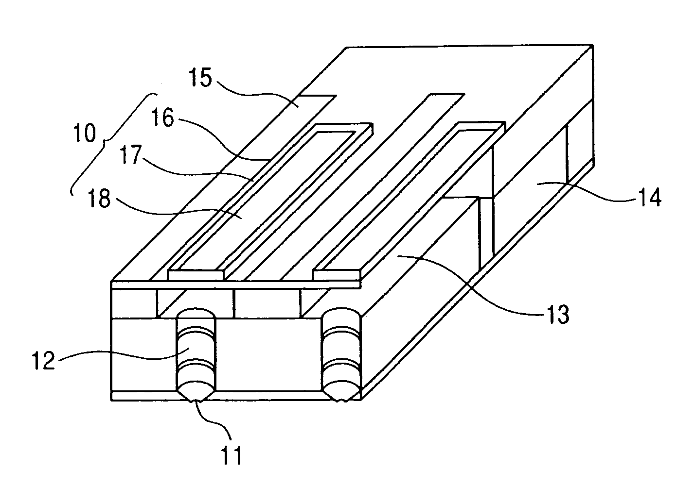
[0114] First, as a substrate (substrate 20) of the main body, an Si substrate of (100) orientation was used. On the Si substrate, a stabilized zirconia YSZ (Y2O3—ZrO2) film serving as the vibration board 15 and the buffer layer 19 were formed so as to have (100) orientation by a sputtering apparatus (L-210-FH, manufactured by ANELVA). The vibration board 15 and the buffer layer 19 were epitaxially grown by supplying a power of 60W between the Si substrate and the target in a chamber containing Ar and O2 gas as ion formation gases and set at an inner pressure of 1.0 Pa while heating the Si substrate at 800° C. As a result, single orientation (100) films of the vibration board 15 and the buffer layer 19 of 200 nm thick were obtained.

[0115] Next, a Pt lower electrode 16 was formed on the vibration board 15 in the same manner as in a formation method of the vibration board 15. More specifically, the lower electrode was epitaxially grown by supplying a power of 100 W between the vibrati...

example 2

[0123] The same procedure as in Example 1 was repeated to form a liquid discharge head except that the target composition for a piezoelectric member was prepared from PbO, MgO, Nb2O5 and PbTiO3 in accordance with the following formula.

[0124]2>

[0125] (Pbk, αl)x(Mgm, Nbn, Tio, βp)yO3, where 1≦x / y<1.2, k=1, l=0, m+n+o+p=1, m=0.22, n=0.44, o=0.33, and p=0.

[0126] The piezoelectric member obtained in the aforementioned method has a uniaxial-oriented (100) single crystal formed of a phase mixture of a pseudo cubic system and a tetragonal system.

example 3

[0127] The same procedure as in Example 1 was repeated to form a liquid discharge head except that the target composition for a piezoelectric member was prepared from PbO, NiO, Nb2O5 and PbTiO3 in accordance with the following formula.

[0128]3>

[0129] (Pbk, βl)x(Nim, Nbn, Tio, βp)yO3, where 1≦x / y<1.2, k=1, l=0, m+n+o+p=1, m=0.20, n=0.40, o=0.40, and p=0.

[0130] The piezoelectric member obtained in the aforementioned method has a uniaxial-oriented (100) single crystal formed of a phase mixture of a pseudo cubic system and a tetragonal system.


PUM

PropertyMeasurementUnit
Thicknessaaaaaaaaaa
Thicknessaaaaaaaaaa
Temperatureaaaaaaaaaa

Abstract

A perovskite type oxide of a single crystal structure or a uniaxial-oriented crystal structure represented by ABO3 where site A includes Pb as a main component and site B includes a plurality of elements, wherein the perovskite type oxide includes a plurality of crystal phases selected from the group consisting of tetragonal, rhombohedral, orthorhombic, cubic, pseudo-cubic and monoclinic systems and the plurality of crystal phases are oriented in the direction of <100>.

Description

BACKGROUND OF THE INVENTION [0001] 1. Field of the Invention [0002] The present invention relates to a perovskite type oxide material that can be used as a piezoelectric member, a piezoelectric element, a liquid discharge head and liquid discharge apparatus using the same, and a method of producing the perovskite type oxide material. [0003] 2. Description of the Related Art [0004] A piezoelectric member has piezoelectric characteristics, that is, converting electric energy into mechanical energy, namely, converting electric energy into mechanical displacement, stress or vibration, and vice versa. A conventional piezoelectric element is formed by sandwiching a thin film of such a piezoelectric member between electrodes. When an electric field is applied to the piezoelectric member, the member causes displacement. In contrast, when the electric field is removed from the member, the state of displacement returns to the original state. A piezoelectric element uses such piezoelectric cha...

Claims


Application Information

Patent Timeline
IPC IPC(8): C04B35/495C04B35/00
CPCC04B35/472H01L41/0973C04B2235/3206C04B2235/3208C04B2235/3213C04B2235/3215C04B2235/3224C04B2235/3227C04B2235/3234C04B2235/3251C04B2235/3258C04B2235/3272C04B2235/3275C04B2235/3279C04B2235/3284C04B2235/3286C04B2235/3293C04B2235/3294C04B2235/3298C04B2235/76C04B2235/762C04B2235/765C04B2235/768C04B2235/787C04B2235/79H01L41/1875H01L41/316C04B35/499H10N30/2047H10N30/8548H10N30/076
Inventor MATSUDA, TAKANORIAOKI, KATSUMIIFUKU, TOSHIHIROTAKEDA, KENICHIFUKUI, TETSUROFUNAKUBO, HIROSHIYOKOYAMA, SHINTARO
Owner CANON KK
Learn More