
External adjustment mechanism for a camera lens and electronic imager

a technology of external adjustment mechanism and electronic imager, which is applied in the field of electronic devices, can solve the problems of affecting the quality of captured images, and the delicate operation of screwing the lens unit into the housing, so as to achieve the effect of reducing manufacturing costs, reducing manufacturing costs, and improving quality

Active Publication Date: 2007-03-15
NANCHANG O FILM OPTICAL ELECTRONICS TECH CO LTD
View PDF17 Cites 31 Cited by
  • Summary
  • Abstract
  • Description
  • Claims
  • Application Information

AI Technical Summary

Benefits of technology

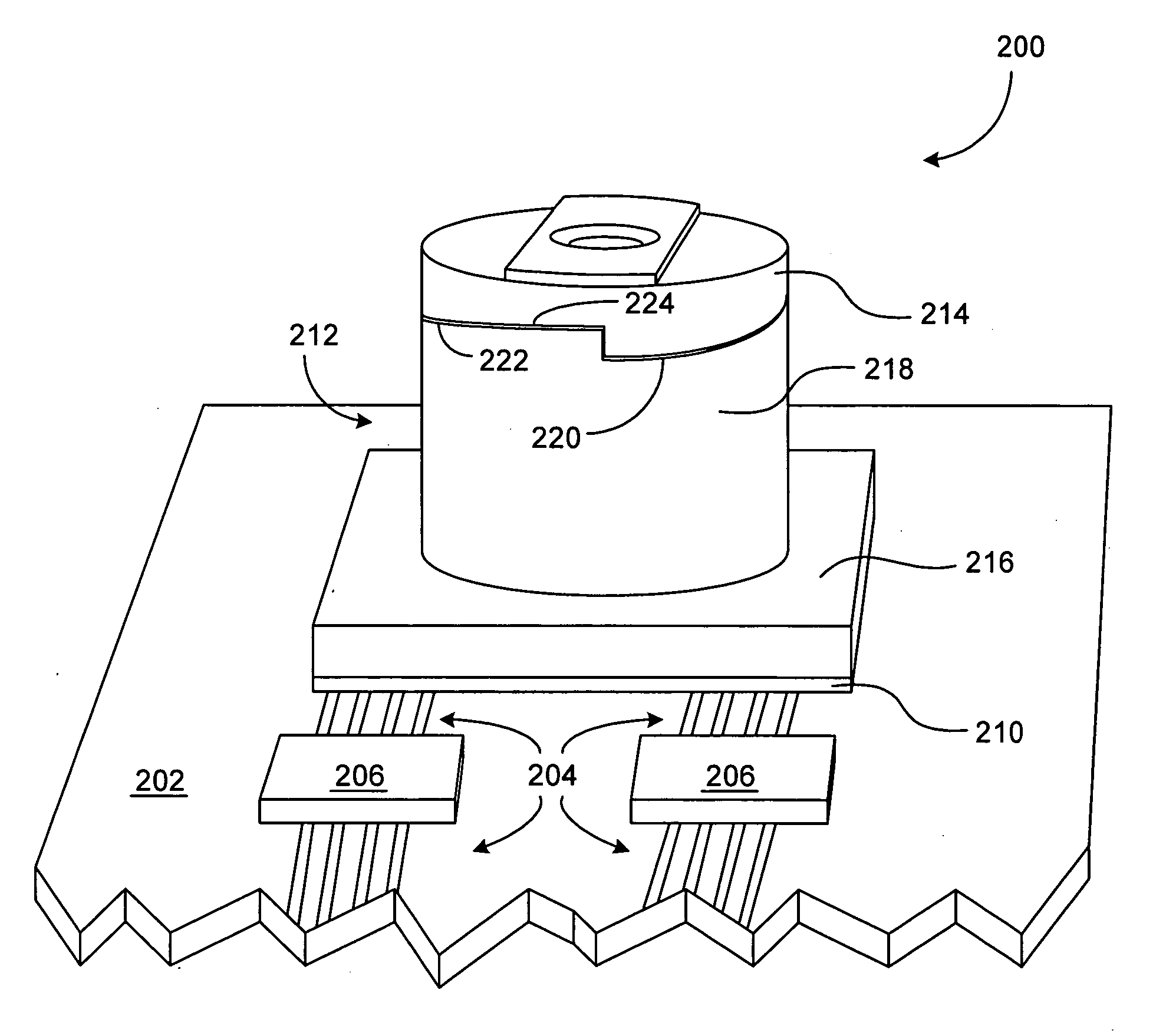
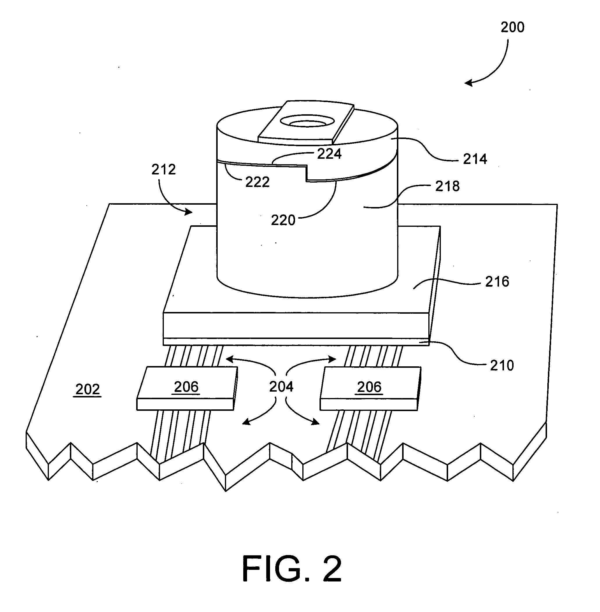
The present invention provides a digital camera module with a focus mechanism that is located outside of the camera module. This prevents particulate debris from being created inside the camera module and makes it easier to manufacture and assemble. The focus mechanism includes a ramp and a complementary ramp or guide member to ensure the lens unit remains centered and aligned with the image capture device. The camera module can be used in various camera-hosting devices such as mobile phones, computers, and other portable electronic devices.

Problems solved by technology

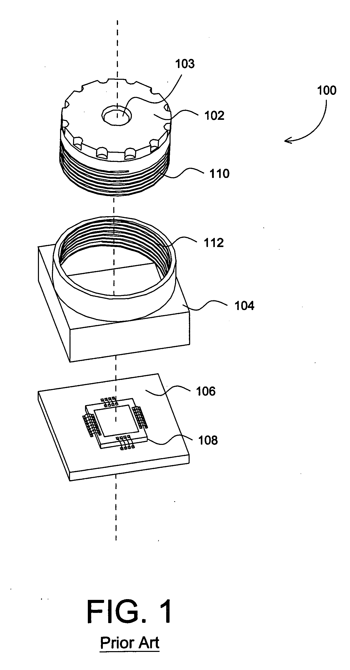
For example, threads are relatively difficult and expensive to manufacture on small optical components.
In addition, small fine threads make screwing the lens unit into the housing a delicate operation.
Such particulate debris noticeably degrades the quality of the captured images.
Because digital camera modules are not easily disassembled and cleaned, particulate matter inside the module is particularly undesirable.
It should also be noted that although threaded components are used here as an example, other types of focusing components located inside housing 104 can similarly produce particulate debris that reduces the quality of the captured images.

Method used


Image

  • External adjustment mechanism for a camera lens and electronic imager
  • External adjustment mechanism for a camera lens and electronic imager
  • External adjustment mechanism for a camera lens and electronic imager

Examples


Embodiment Construction

[0024] The present invention overcomes the problems associated with the prior art by providing a system and method for focusing a digital camera module that is inexpensive to produce and where the focusing mechanism is located outside of the housing that houses imaging components of the camera module, such that particulate debris is less likely to contaminate the imaging components and degrade the quality of the captured images. In the following description, numerous specific details are set forth (e.g., particular examples focus mechanisms, substrate type and attachment, etc.) in order to provide a thorough understanding of the invention. Those skilled in the art will recognize, however, that the invention may be practiced apart from these specific details. In other instances, details of well known camera module manufacturing practices (e.g., automated focus processes, materials selection, molding processes, etc.) and components (e.g., electronic circuitry, device interfaces, etc.)...


PUM


Abstract

A novel digital camera module includes an image capture device, a lens unit, a housing for receiving the lens unit and positioning the lens unit with respect to the image capture device, and a focus mechanism disposed on the outside of the housing and operative to move the lens unit along an axis when the lens unit is rotated about the axis. In a particular embodiment, the focus mechanism includes at least one ramp formed on the housing and at least one complementary ramp formed on the lens unit. In another embodiment, the focus mechanism includes a thread set formed on the outside of the housing for engaging a complementary thread set on a sleeve of the lens unit. In still another embodiment, the focus mechanism includes an inclined groove formed on one of the housing and the lens unit, and a groove follower disposed on the other of the housing and the lens unit. The external adjustment mechanism prevents particulates generated during a focus operation from contaminating the sensor array of the image capture device.

Description

BACKGROUND OF THE INVENTION [0001] 1. Field of the Invention [0002] The present invention relates generally to electronic devices, and more particularly to digital camera modules. Even more particularly, the present invention relates to a system for focusing a digital camera module that prevents debris and particulate matter produced by the focusing process from contaminating the sensor array of an image capture device. [0003] 2. Description of the Background Art [0004] Digital camera modules are currently being incorporated into a variety of electronic devices. Such camera hosting devices include, but are not limited to, cellular telephones, personal data assistants (PDAs), and computers. The demand for digital camera modules continues to grow as the ability to incorporate the camera modules into host devices expands. Therefore, one design goal of digital camera modules is to make them as small as possible so that they will fit into an electronic device without substantially increa...

Claims


Application Information

Patent Timeline
Patent Type & Authority Applications(United States)
IPC IPC(8): G03B3/00
CPCG02B7/02H04N5/2254G03B3/02G02B7/04H04N23/55
Inventor SHANGGUAN, DONGKAIBOGUE, ELAINE B.KALE, VIDYADHAR SITARAMTAM, SAMUEL WAISINGMORTON, RAY H.
Owner NANCHANG O FILM OPTICAL ELECTRONICS TECH CO LTD
Learn More