
Projection display apparatus and optical filter

Inactive Publication Date: 2007-03-15
CHUNGHWA PICTURE TUBES LTD
View PDF7 Cites 5 Cited by
  • Summary
  • Abstract
  • Description
  • Claims
  • Application Information

AI Technical Summary

Benefits of technology

[0009] In view of this, one object of the present invention is to provide a projection display apparatus capable of extending lifetime of the light source and optical devices.
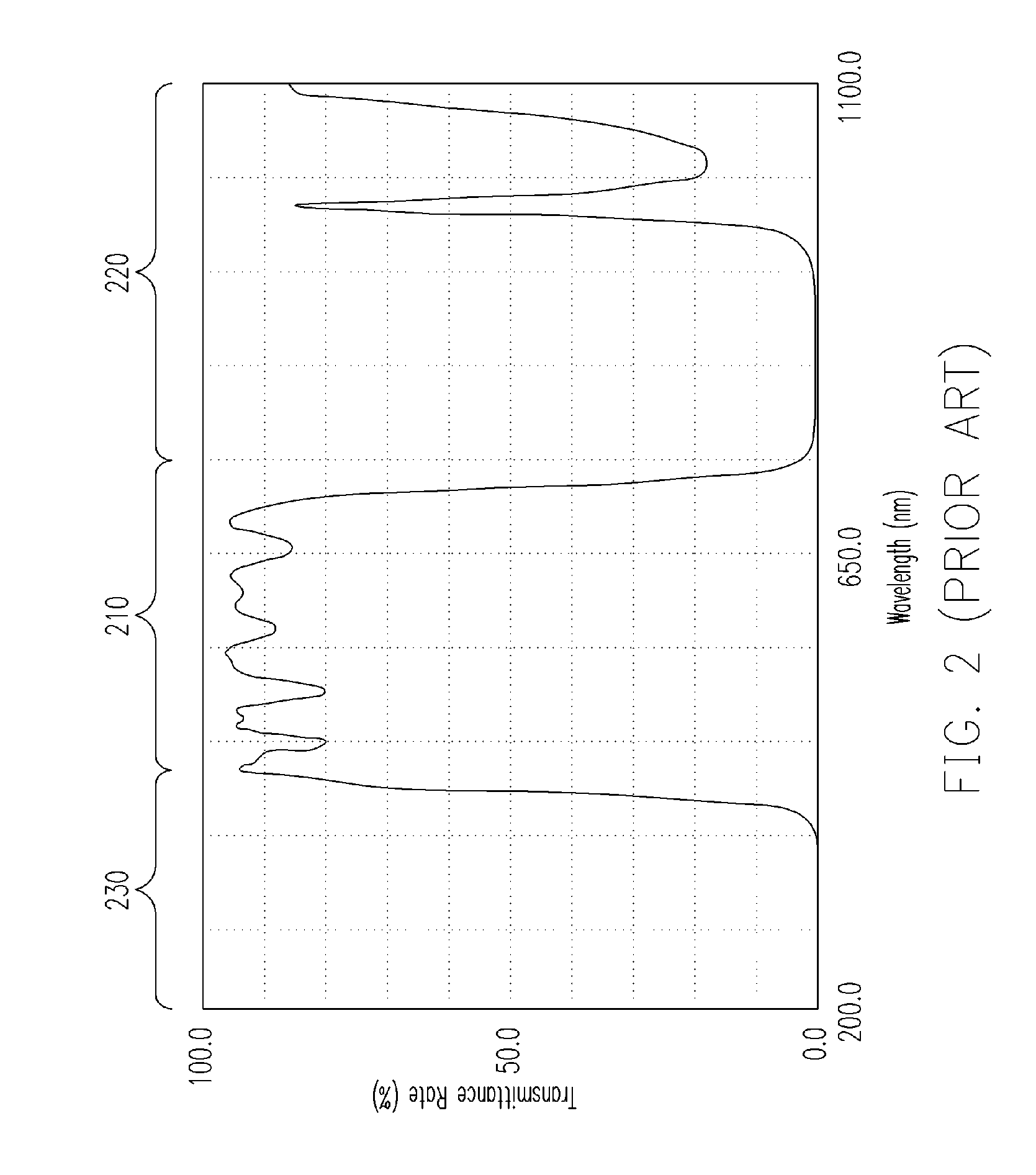
[0024] Based on the present invention, because of the adoption of the YAG filter owning merits, including the ability of absorbing the infrared rays and a high coefficient of thermal conductivity, heat dissipation of the projection display apparatus can be improved and the accumulated heat generated by the infrared rays that cause shortened lifetime of the light source can be prevented. Moreover, the coating layer disposed on the surface of the YAG filter is helpful in reflecting the UV lights and raising the transmittance rate of visual lights, so not only the damages of optical devices made of organic materials can be avoided but also utility efficiency of lights can be increased.

Problems solved by technology

Despite the merit of high brightness, there are still many drawbacks accompanied with those light sources, such as high power consumption, short lifetime, and immense heat generation and so forth.
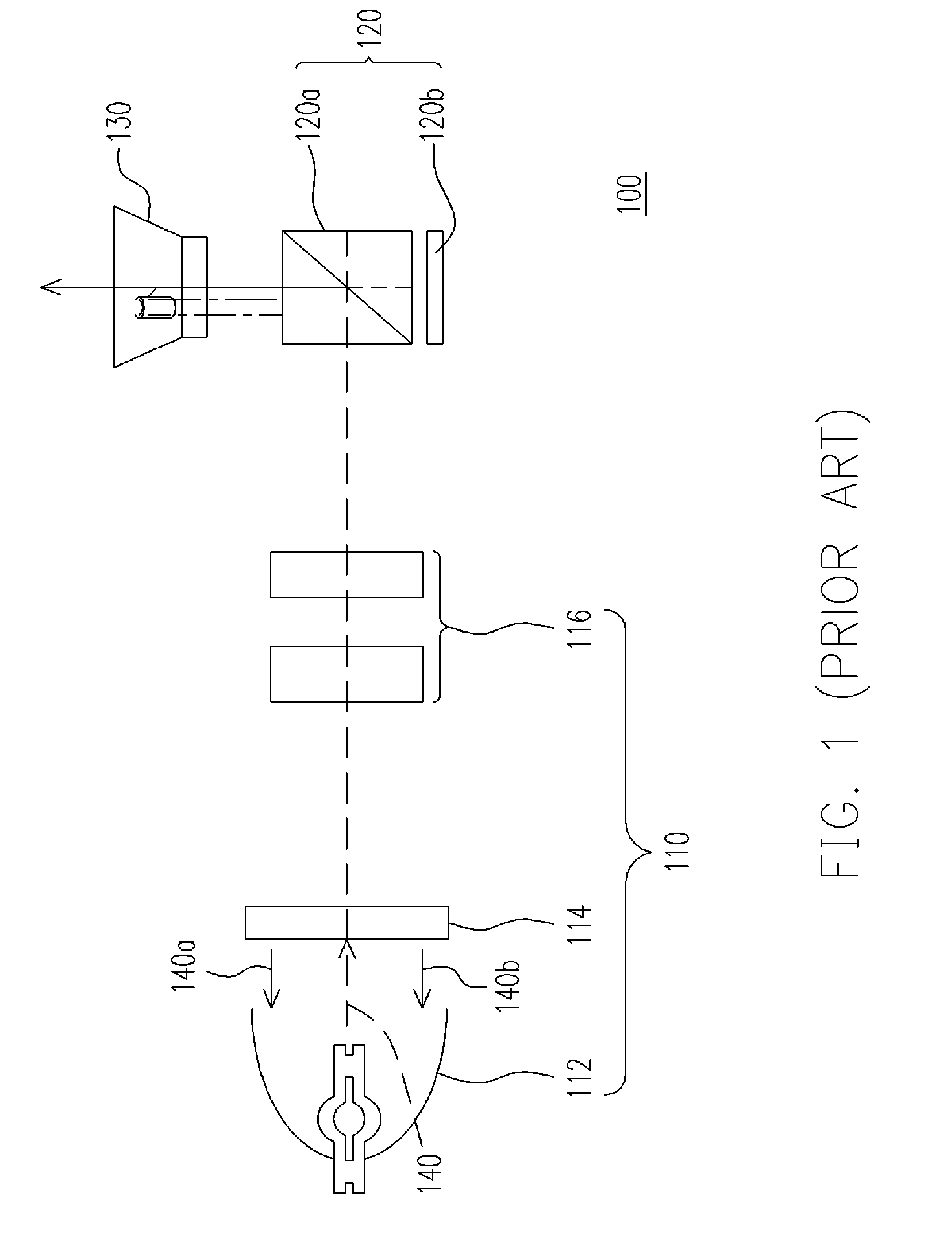
Among those drawbacks, in particular, the immense heat generated by light sources often leads to shortened lifetime of light sources and damages of optical devices in the projection display apparatus.
The optical devices (such as the lens set 116 shown in FIG. 1) made of organic materials would probably get damaged as well.

Method used


Image

  • Projection display apparatus and optical filter
  • Projection display apparatus and optical filter
  • Projection display apparatus and optical filter

Examples


first embodiment

The First Embodiment

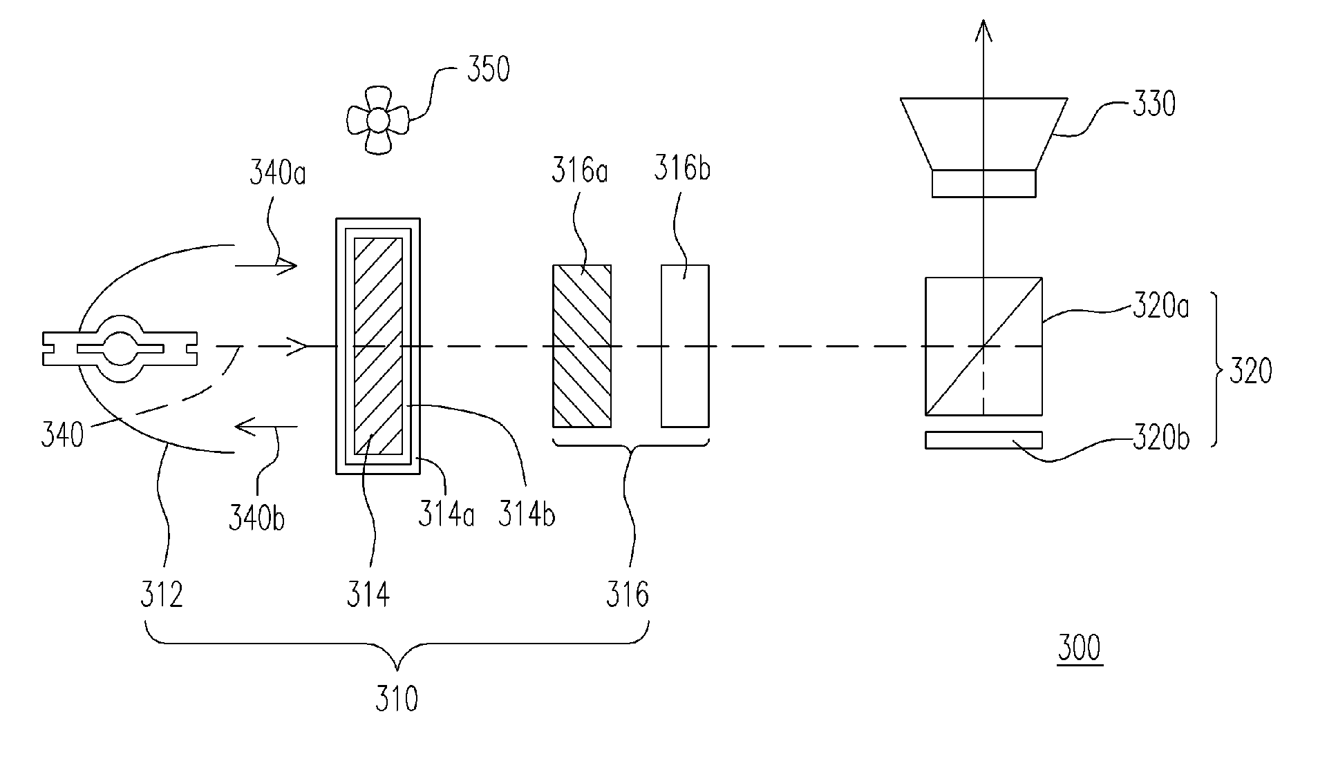
[0034]FIG. 3 schematically shows a projection display apparatus according to one preferred embodiment of the present invention. Referring to FIG. 3, the projection display apparatus 300 may comprise a lighting system 310, a projection lens 330 and a display unit 320, for example.

[0035] The lighting system 310 may comprise a light source 312, a lens set 316 and an Yttrium Aluminum Garnet filter (YAG filter) 314, for example. The light source 312 is suitable for supplying a light beam 340, and in one preferred embodiment the light source 312 can be an ultra high pressure (UHP) lamp which is filled with high-pressure mercury-vapor. The lens set 316 is disposed on the transmission path of the light beam 340, and in one preferred embodiment it may comprise a PS converter 316a for converting the P-direction and S-direction polarized lights of the light beam 340 and a condenser lens 316b for focusing the light beam 340 to enhance the intensity of the light beam 340.

[0...

second embodiment

The Second Embodiment

[0050]FIG. 7 schematically shows an optical filter according to one preferred embodiment of the present invention. Referring to FIG. 7, the optical filter 500 comprises an Yttrium Aluminum Garnet filter (YAG filter) 510 and at least one coating layer 520. Wherein, the coating layer 520 is disposed on the surface of the YAG filter 510. Except being able to absorb the infrared rays, the YAG filter 510 owns the characteristics including a high coefficient of thermal conductivity, a high melting point, a high transmittance rate, robust mechanical strength, and high insulation capability.

[0051] In one preferred embodiment of the present invention, the coating layer 520, for example, is an anti-reflective coating (AR coating) 522 used to raise the transmittance rate of visual lights, and a material of this AR coating, includes MgF2 or Na3AlF6 for example.

[0052] In another embodiment of the present invention, the coating layer 520 mentioned above, for example, is an ...


PUM


Abstract

A projection display apparatus including a lighting system, a projection lens and a display device. The lighting system has a light source, a lens set, and an Yttrium Aluminum Garnet filter (YAG filter) is provided. The light source is suitable for providing a light beam. The lens set is disposed on the transmission path of the light beam. The YAG filter is disposed between the light source and the lens set and on the transmission path of the light beam as well. Additionally, the projection lens is disposed on the transmission path of the light beam. The display device is disposed between the lighting system and the projection lens and on the transmission path of the light beam as well. The projection apparatus having the YAG filter is benefited in dispelling the heat of the light source and optical devices, thereby extending lifetime of the light source and optical devices.

Description

BACKGROUND OF THE INVENTION [0001] 1. Field of Invention [0002] The present invention relates to a projection display apparatus and an optical filter. In particular, the present invention relates to an optical filter capable of absorbing the infrared rays, and heat dissipation of the projection display apparatus is improved by using the optical filter. [0003] 2. Description of Related Art [0004] In general, the projection display apparatuses in the prior art are applied in the displaying apparatuses of the front-projection type or large-screen rear-projection type, so the light sources required must be able to supply higher total luminance to have the projection image with higher brightness. Therefore, halogen lamps or a variety of high-pressure mercury lamps are widely used as light sources in projection display apparatuses. Despite the merit of high brightness, there are still many drawbacks accompanied with those light sources, such as high power consumption, short lifetime, and ...

Claims


Application Information

Patent Timeline
IPC IPC(8): G03B21/16
CPCG03B21/26
Inventor YANG, CHING-ANWU, SHIH-MINMO, CHI-NENG
Owner CHUNGHWA PICTURE TUBES LTD
Learn More