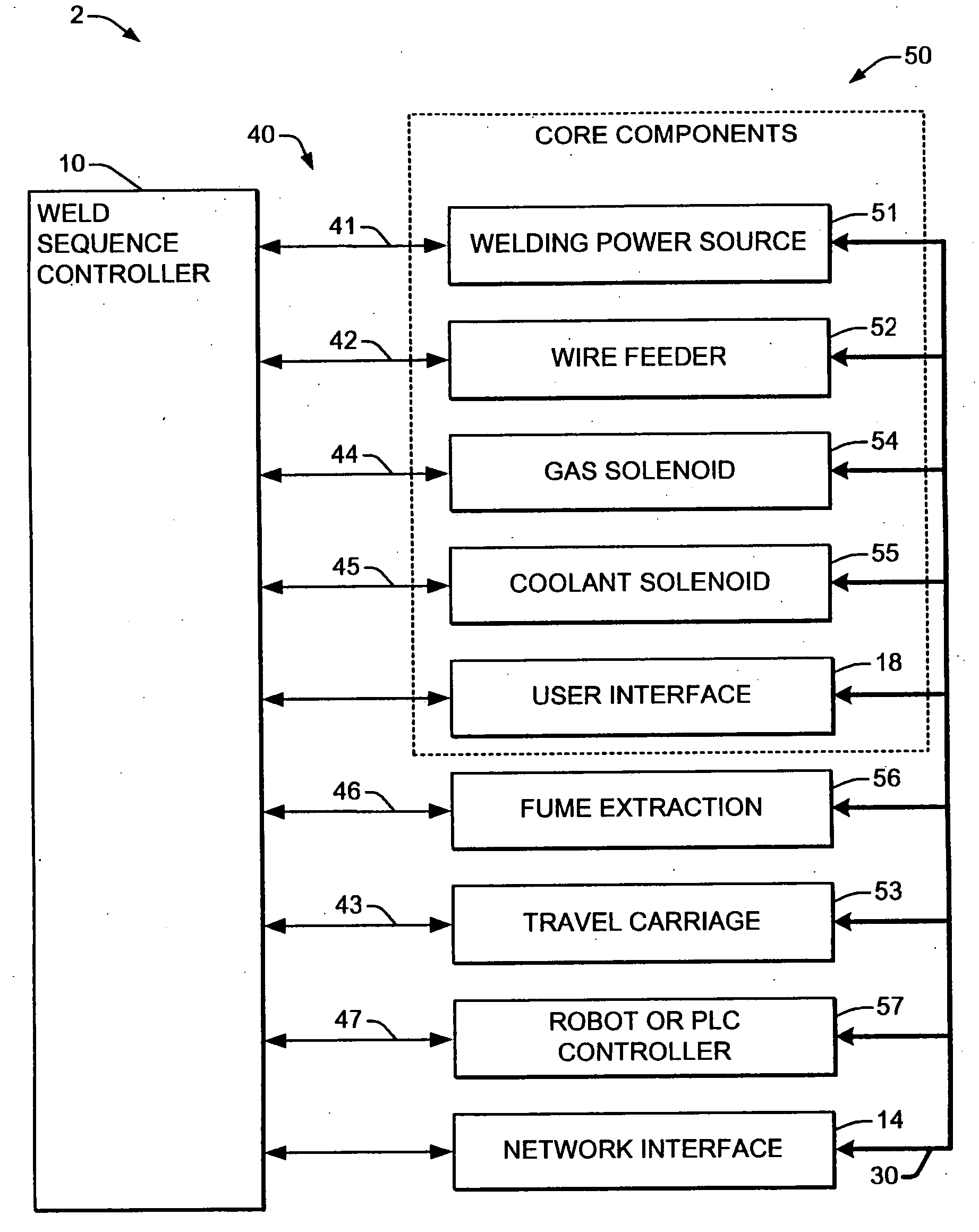
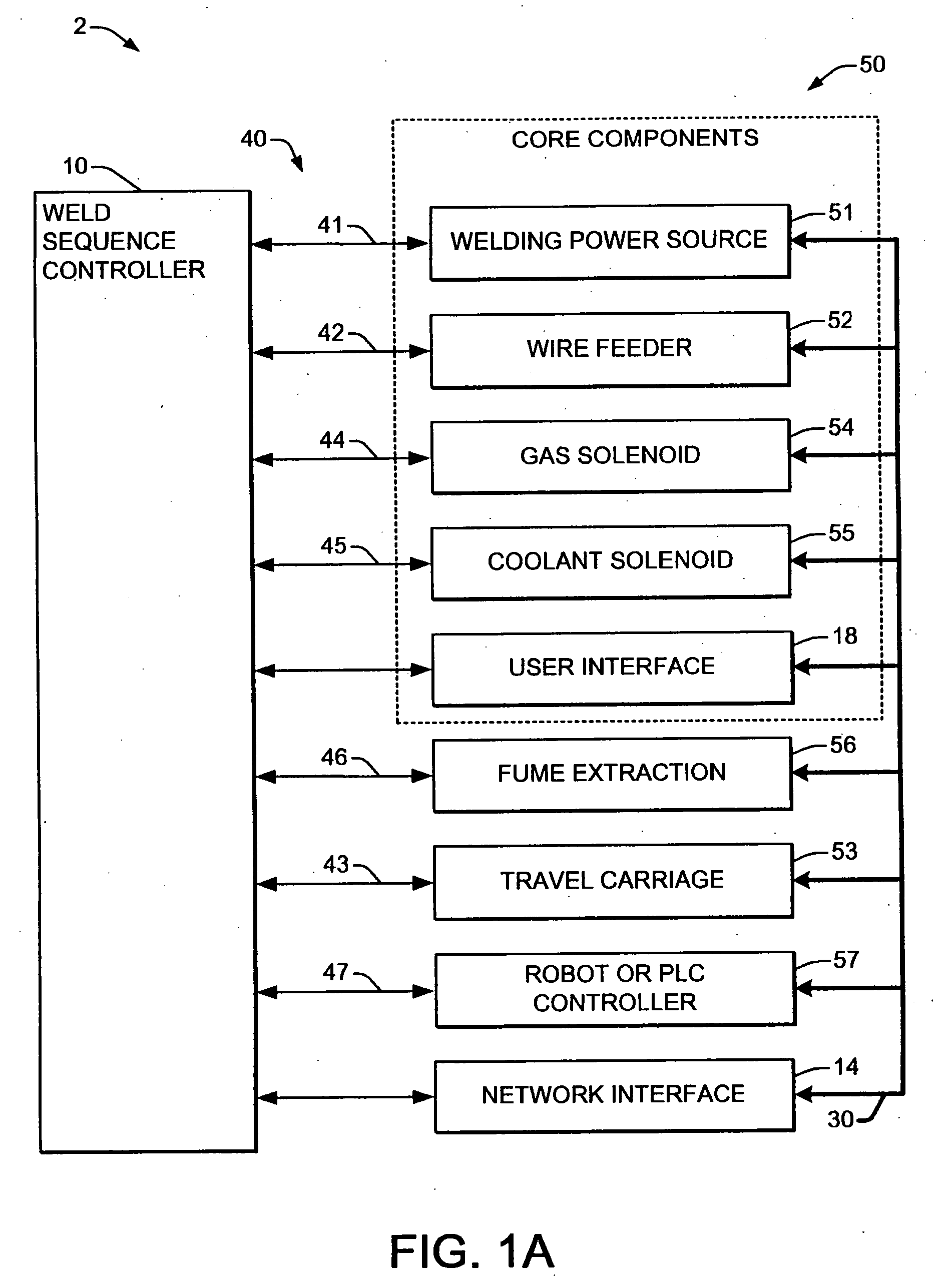
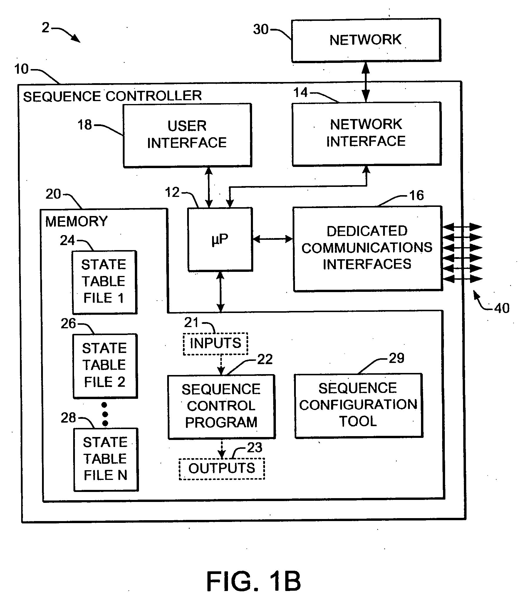
[0007] In accordance with one or more aspects of the invention, a welding system is provided, having two or more system components including a power source that provides a welding
signal to a
welding process, and a reprogrammable sequence controller. The sequence controller receives inputs from one some or all of the system components and provides outputs to perform a welding operation. A
processing component is included in the sequence controller, along with a sequence control program that is
executable by the
processing component, and one or more sequence control state table files are provided which are accessible by the processing component. The state table files include a plurality of entries, each of which corresponds to a segment or state of a welding operation, where the control program is executed in accordance with the state table file entries and the current sequencer inputs to perform a multiple state welding operation as a series of states. By this unique architecture, any particular welding operation can be effectively represented as a number of entries in a state table file, and a somewhat generic
executable sequence control program can interpret the appropriate instructions or routines to be executed for a given operational state according to the state table entries. One particular
advantage of the present invention lies in the ability to reprogram the operation of a welding system by simply modifying an existing state table file or creating a new table file and storing the same in a
data store accessible by the processing component. This can be done using a configuration tool, such as a
software program on a
laptop or desktop computer, PDA,
Ethernet network connection,
cell phone, blackberry,
wireless communications device, etc., or configuration may be done via a
user interface and a configuration tool integrated into a system component (e.g., wire feeder, power source, sequence controller, etc.), where the sequence control program need not be recompiled or otherwise modified. Once the state table file is stored, the executable sequence control program is executed, with the current system inputs being obtained along with a current state table file entry.
[0008] Each state table file entry is essentially the shell providing an instruction indicator or identifier telling the executable control program what instructions or routines are to be executed, along with one or more parameters and conditional checks with corresponding next state
branch indicators. The state table entries individually define one segment of the weld cycle and one or more states are combined in a logical sequence that defines the entire weld cycle, where the conditional check(s) associated with each state entry determine the conditions under which each state is completed and which state entry will be the next system state. One or more instruction identifiers are provided in each state table entry, which identify an executable instruction or routine of the sequence control program, and corresponding instruction parameters are provided, for example, where the instruction identifier may indicate that the sequence control program is to regulate the welding power source output to a work point value specified by the parameter found in the state table file entry or a value provided at a
user interface knob in the system. The processing component generates the sequence controller outputs accordingly, for instance, by providing appropriate control signals to the power source, wire feeder, etc., to effectuate the specified function(s) of the current state. The table file entries also include at least one exit condition identifier corresponding to a welding system condition, along with a next state identifier indicating a next entry corresponding to the exit condition identifier. In this manner, the state based system operation can
branch to appropriate states depending on current system conditions (e.g., determined by the current sequencer inputs,
timer conditions, etc.), whereby the state table file may be constructed to account for any number of situations possible in a welding operation. In one implementation illustrated and described below, the processing component obtains a current sequence control state table file entry from the table file, obtains the current inputs from the welding system components, and executes one or more executable instructions or routines of the sequence control program identified by an instruction identifier of the current entry using an instruction parameter of the current entry to provide the sequence controller outputs. In addition, the processing component determines whether a welding system condition identified by an exit condition identifier of the current table file entry is satisfied according to the current sequence controller inputs, and if so, selectively obtains a next sequence control state table file entry corresponding to the exit condition identifier. The entry may also include an optional action identifier corresponding to the exit condition identifier, where the action identifier identifies an executable instruction or routine of the sequence control program that is executed if the specified exit condition has been satisfied.
[0009] Other aspects of the invention relate to tools for configuring a welding system sequence controller, with a
user interface for rendering state table file entries to a user, where the sequence control state table file entries individually include an instruction identifier, a corresponding instruction parameter, an exit condition identifier, and a next state identifier, and the tool allows the user to modify the entries to create or modify a sequence control state table file and to store the sequence control state table file. In one embodiment, the user interface comprises a display, such as a graphic display or other display integrated into a welding power source or wire feeder, where the display renders individual sequence control state table file entries to the user, and the user is allowed to select the instruction identifier, to set the instruction parameter or to link the instruction parameter with an adjustable user interface control component, to set the exit condition identifier, and to set the next state identifier for each the sequence control state table file entry.


