
Film Forming Apparatus And Jetting Nozzle

Inactive Publication Date: 2007-03-08
BROTHER KOGYO KK +1
View PDF7 Cites 10 Cited by
  • Summary
  • Abstract
  • Description
  • Claims
  • Application Information

AI Technical Summary

Benefits of technology

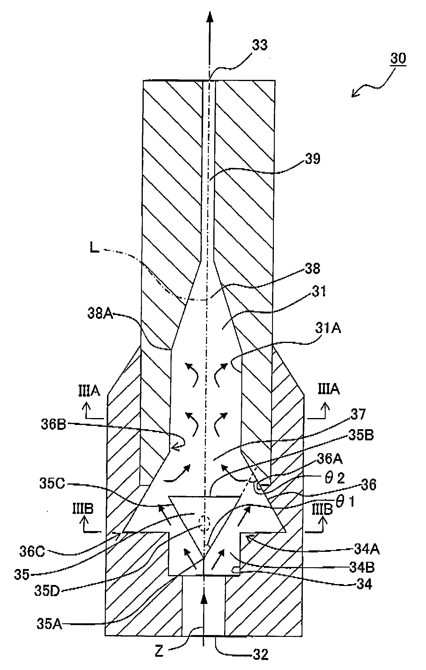
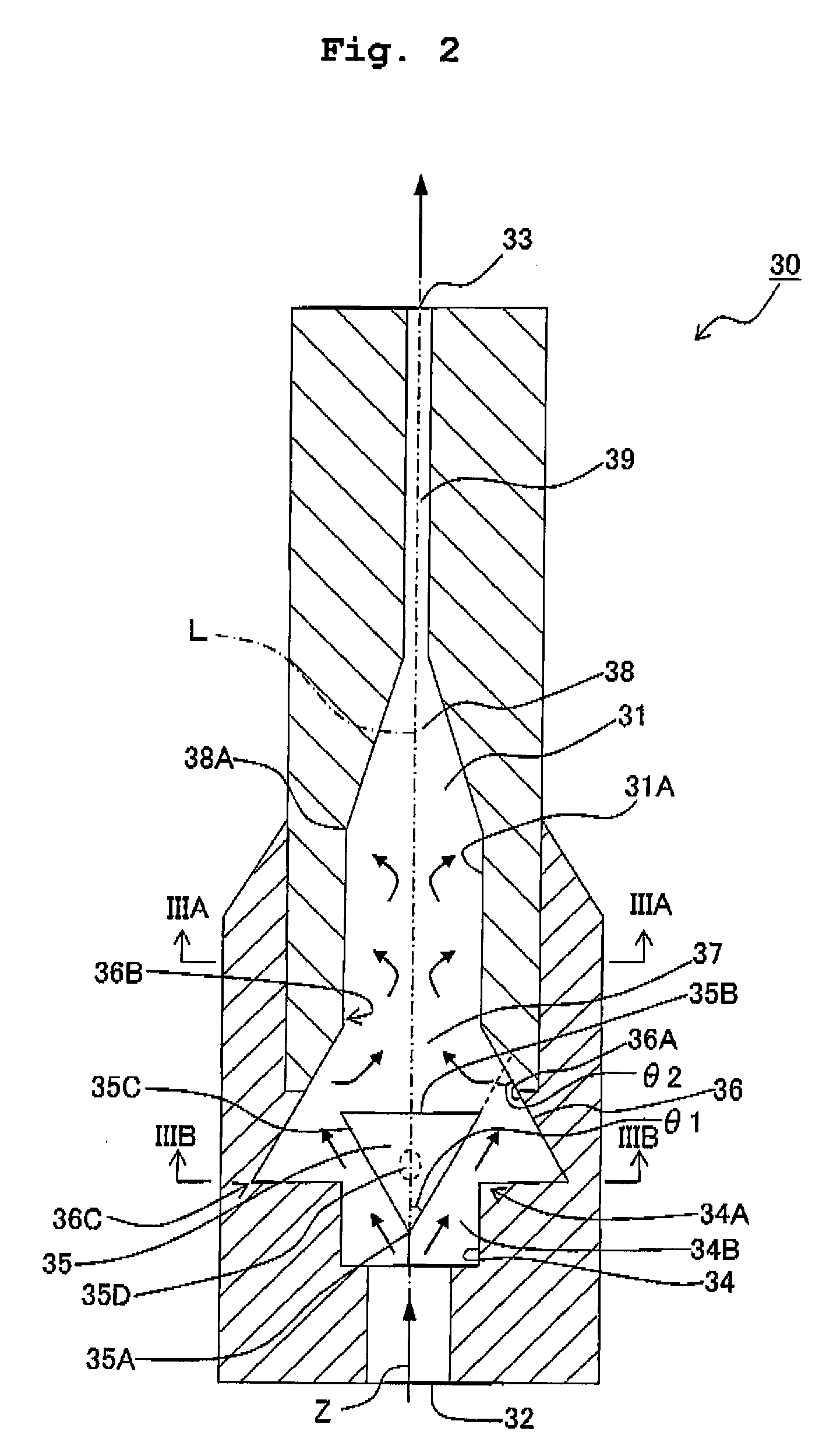
[0020] In the film forming apparatus and the jetting nozzle of the present invention, a flow velocity of the aerosol, which has entered into the internal passage of the nozzle, is increased while passing through the narrowed channel, and the aerosol reaches the collision portion which is provided on the downstream of the narrowed channel. At this time, among particulate material (material particles) included in the aerosol, minute particles having a small mass are turned around a wall surface of the collision portion and flowed toward downstream of the flow of the aerosol, but aggregated particles having a comparatively larger mass cannot turn around the collision portion because of a large inertial force, and thus collide against the collision portion to be pulverized or crushed. Thus, the aggregated particles are crushed and are thus supplied from the nozzle in the form of fine particles. Therefore, it is possible to form a thin and uniform film on a process-objective material.
[0031] In the film forming apparatus of the present invention, an inner-wall surface of the internal passage, which surrounds the obstacle member, may be tapered toward downstream of the flow of the aerosol. In this case, the inner-wall surface formed to be taper shaped is made to be the collision portion, and an area of the internal passage on the upstream side becomes the expanded portion. Thus, it is possible to form the collision portion and the expanded portion by a single structure, namely the tapered inner-wall surface. Consequently, it is possible to crush the aggregated particles while avoiding complication of the structure of the jetting nozzle, and to form a uniform film.

Problems solved by technology

Since these aggregated particles have a large mass, collision energy at the time of colliding on the substrate is substantial, which in turn causes damage to the film and the like, thereby serving as a cause to hinder the formation of a thin and uniform film.

Method used


Image

  • Film Forming Apparatus And Jetting Nozzle
  • Film Forming Apparatus And Jetting Nozzle
  • Film Forming Apparatus And Jetting Nozzle

Examples


first embodiment

[0042] A first embodiment in which the present invention is embodied will be explained below with reference to FIG. 1 to FIG. 3.

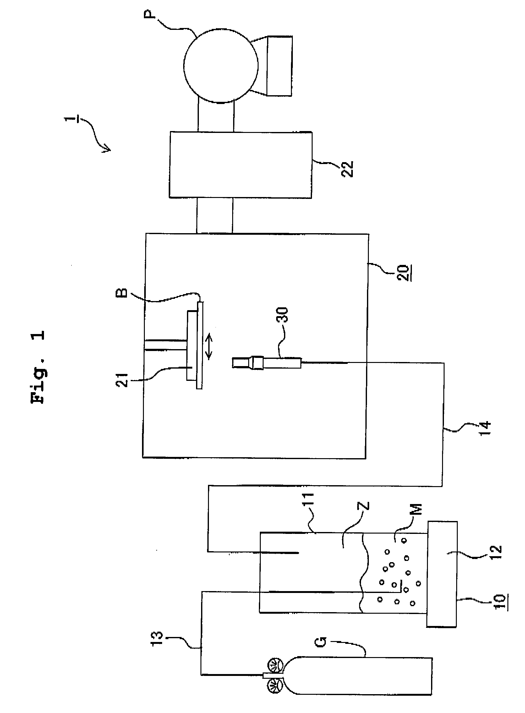
[0043]FIG. 1 shows a schematic diagram of a film forming apparatus 1 in which the present invention is embodied. The film forming apparatus 1 includes an aerosol generator 10 which forms an aerosol Z by dispersing material particles (particulate material) M in a carrier gas, and a film forming chamber 20 in which the aerosol Z is jetted from a jetting nozzle 30 so as to make the material particles M in the aerosol Z to adhere to a substrate B (process-objective material).

[0044] The aerosol generator 10 includes an aerosol chamber 11 which is capable of accommodating the material particles M therein, and a vibration unit 12 which is attached to the aerosol chamber 11 and which causes the aerosol chamber 11 vibrate. A gas cylinder G for introducing the carrier gas is connected to the aerosol chamber 11 via an introduction pipe 13. An end of the introduction...

second embodiment

[0067] A second embodiment of the present invention will be explained as below with reference to FIG. 4 and FIG. 5. The second embodiment differs from the first embodiment mainly in that, in the second embodiment, a surface facing the flow of the aerosol 2 in a block 45 is a circular-arc shaped surface, and that a collision portion 46 is formed to project in an internal passage 41. Same reference numerals are designed to part or component same as those in the first embodiment, and the explanation therefor is omitted.

[0068] A jetting nozzle 40 of the second embodiment is used in the film forming apparatus 1 similarly as in the first embodiment. The jetting nozzle 40 is formed to be circular cylindrical shaped and having the internal passage 41 formed therein in a similar manner as in the first embodiment. An opening on a side of a lower end of the internal passage 41 defines a supply port 42, and an opening on a side of an upper end of the internal passage 41 defines a jetting port ...

third embodiment

[0079] A third embodiment of the present invention will be explained as below with reference to FIG. 6 and FIG. 7. The third embodiment differs from the first embodiment mainly in that in the third embodiment, an inner-wall surface 58B of a throttle portion 58 is made to be a collision surface by providing a block 55 at an inlet of the throttle portion 58. Same reference numerals are designated for structures (parts or components) which are similar as in the first embodiment, and the explanation therefor will be omitted.

[0080] A jetting nozzle 50 of the third embodiment can be used in a film forming apparatus 1 which is similar as that in the first embodiment. The jetting nozzle 50 is formed to be circular-cylindrical shaped and includes an internal passage 51 formed therein similarly as in the first embodiment. An opening on a side of a lower end of the internal passage 51 defines a supply port 52, and an opening on a side of an upper end of the internal passage 51 defines a jetti...


PUM

PropertyMeasurementUnit
Fractionaaaaaaaaaa
Angleaaaaaaaaaa
Angleaaaaaaaaaa

Abstract

A film forming apparatus includes an aerosol generating section which generates an aerosol; a jetting nozzle having an internal passage formed therein and through which the aerosol flows, the internal passage having one end serving as a supply port of the aerosol and having other end serving as a jetting port of the aerosol; a narrowed channel which is provided in the internal passage and which has a channel area narrower than a channel area on an upstream of the narrowed channel; and a collision portion which is provided in the internal passage on a downstream of the narrowed channel, and against which a flow of the aerosol passed through the narrowed channel collides. Since the aggregated particles are crushed and supplied from the jetting nozzle in the form of fine particles, a thin and uniform film can be formed on the process-objective material.

Description

CROSS REFERENCE TO RELATED APPLICATION [0001] The present application claims priority from Japanese Patent Application No. 2005-243033, filed on Aug. 24, 2005, the disclosure of which is incorporated herein by reference in its entirety. BACKGROUND OF THE INVENTION [0002] 1. Field of the Invention [0003] The present invention relates to a film forming apparatus which forms a film of a ceramics material and a metallic material by using an AD (aerosol deposition) method, and a jetting nozzle used in the film forming apparatus. [0004] 2. Description of the Related Art [0005] As a producing method of a piezoelectric film of a piezoelectric actuator used, for example, in an ink-jet head for an ink-jet printer or the like, a method called as an aerosol deposition method (AD method) is available. The AD method is a method of forming a piezoelectric film by jetting a substance (aerosol), in which fine particles of a piezoelectric material such as lead zirconate titanate (PZT) or the like is ...

Claims


Application Information

Patent Timeline
IPC IPC(8): B05B1/14
CPCB05B7/0012B05B7/025B05B7/1404B05B7/1472B05B7/1486C23C30/00C23C4/02C23C4/04C23C4/085C23C4/18C23C4/00C23C4/073
Inventor YASUI, MOTOHIROAKEDO, JUN
Owner BROTHER KOGYO KK
Learn More