Cache system
a cache control and cache technology, applied in the field of distributed cache systems, can solve the problems that traffic occurring in the network may exceed the processing capacity of the cache control server, and achieve the effect of easy adaptation to a large-scale network
- Summary
- Abstract
- Description
- Claims
- Application Information
AI Technical Summary
Benefits of technology
Problems solved by technology
Method used
Image
Examples
first embodiment
[0043] In a distributed cache system of a first embodiment, a distributed cache system which can be adapted to a large-scale network is provided in which cache control servers can be added when the content requests from clients increases, and the requests from clients are processed in a distributed manner by multiple cache control servers.
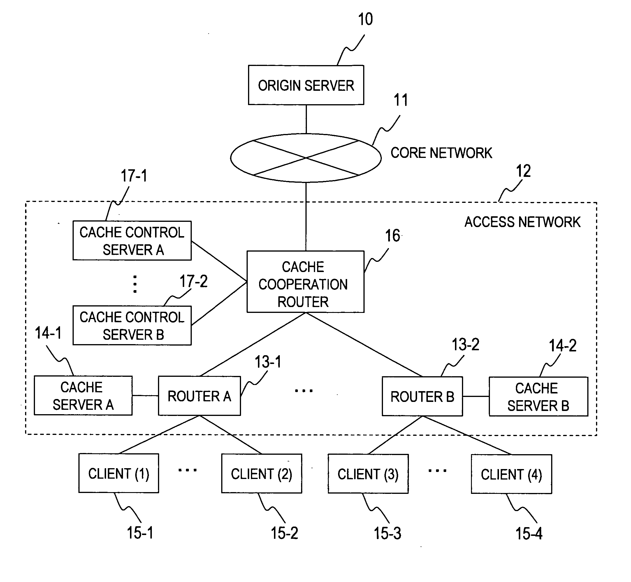
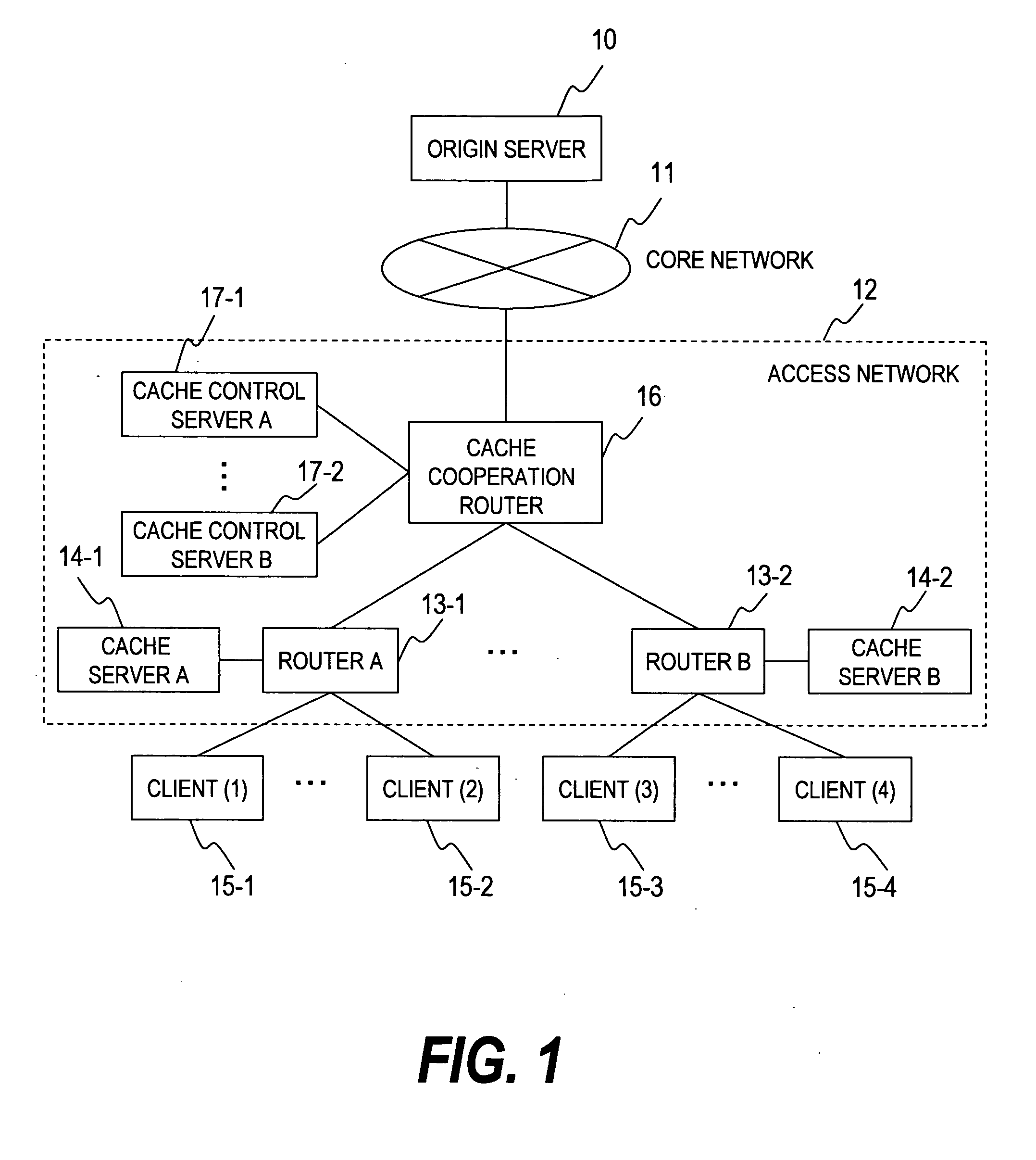
[0044]FIG. 1 is a block diagram which shows an exemplary structure of a distributed cache system according to the first embodiment of the invention.
[0045] The distributed cache system shown in FIG. 1 includes an origin server 10, a core network 11, an access network 12, and multiple clients 15-1 to 15-4.
[0046] The origin server 10 is a computer comprising a processor, a memory, a storage device, and an I / O unit. The storage device stores original data of the content that is requested by the clients. The origin server 10 exists in a network outside of the clients 15-1 or the like, and the origin server and the clients are connected via the core n...
second embodiment
[0142] Next, a distributed cache system according to the second embodiment of the invention will be described.
[0143] The distributed cache system according to the second embodiment is characterized in that the traffic is processed by multiple cache cooperation routers. This system is effective when the requests from the clients increases and cannot be processed by one of the cache cooperation router.
[0144]FIG. 13 is a block diagram which shows an exemplary structure of a distributed cache system according to the second embodiment.
[0145] The distributed cache system of the second embodiment is different from that of the first embodiment as described (FIG. 1) in that it includes multiple the cache cooperation routers and one of the cache control server. In FIG. 13, two cache cooperation routers are provided, however, three or more cache cooperation routers can be provided. The components identical to those in the first embodiment have same reference numerals, and detailed descripti...
third embodiment
[0155] Next, a distributed cache system according to a third embodiment of the invention will be described.
[0156] In the third embodiment, a cache system which enables transmission / receipt of content between domains in the access network having multiple domains will be described.
[0157]FIG. 15 is a block diagram which shows an exemplary structure of a distributed cache system of the third embodiment.
[0158] The components identical to those in the first embodiment have same reference numerals, and detailed description will be omitted.
[0159] The domains 19-1 and 19-2 respectively has a cache system comprising the cache server 14 which stores the content, and the cache control server 17 which controls transmission / receipt of the content information. The cache control server included in the domain sends updated content information to system management server at the time when the information in the content information management table managed by the cache control server itself is upda...
PUM
 Abstract
Description
Claims
Application Information
 - R&D
- Intellectual Property
- Life Sciences
- Materials
- Tech Scout
- Unparalleled Data Quality
- Higher Quality Content
- 60% Fewer Hallucinations
Browse by: Latest US Patents, China's latest patents, Technical Efficacy Thesaurus, Application Domain, Technology Topic, Popular Technical Reports.
© 2025 PatSnap. All rights reserved.Legal|Privacy policy|Modern Slavery Act Transparency Statement|Sitemap|About US| Contact US: help@patsnap.com


