
Intra-thecal catheter and method for cooling the spinal cord and brain

a technology of spinal cord and catheter, which is applied in the direction of therapeutic cooling, optical conversion of sensor output, contraceptive devices, etc., can solve the problems of high mortality, serious paraplegia, and serious paralysis

Inactive Publication Date: 2007-03-01
ELEFTERIADES JOHN
View PDF7 Cites 28 Cited by
  • Summary
  • Abstract
  • Description
  • Claims
  • Application Information

AI Technical Summary

Benefits of technology

"The present invention provides a method for cooling the brain by positioning a cooling catheter within the brain or spinal canal and circulating cooling fluid through the catheter to cool the brain. The technical effects include reducing brain damage during brain surgery or trauma, preventing brain swelling, and improving brain function."

Problems solved by technology

Despite advances in spinal cord protection, paraplegia continues to be a serious complication of descending and thoracoabdominal aortic operations.
Paraplegia has been a serious and vexing problem since the advent of direct thoracic aortic surgery some 40 years ago.
Paraplegia continues to devastate the lives of patients undergoing surgery for thoracic aortic aneurysm; in cases of post-operative paraplegia, mortality is high and, even in survivors, quality of life is devastated.
When aortic clamp time and consequent reduction of spinal perfusion lasts more than 45 minutes, spinal ischemia ensues, often resulting in paralysis.
This continues to be a major issue, both clinically and medico-legally.
Despite good local results, this technique has not been generally adopted, because of concerns about the cumbersome nature of instilling and draining fluid, and because of documented elevation in intra-thecal pressure consequent upon fluid instillation.
Yet, most aortic surgeons do not utilize deep hypothermic arrest for descending and thoracoabdominal operations, out of concern for potential negative effects of deep hypothermia and prolonged perfusion in this setting.
However, these attempts have met with only limited success.
Khanna fails to provide the specificity required for achieving this goal.

Method used


Image

  • Intra-thecal catheter and method for cooling the spinal cord and brain
  • Intra-thecal catheter and method for cooling the spinal cord and brain
  • Intra-thecal catheter and method for cooling the spinal cord and brain

Examples


Embodiment Construction

[0024] The detailed embodiments of the present invention are disclosed herein. It should be understood, however, that the disclosed embodiments are merely exemplary of the invention, which may be embodied in various forms. Therefore, the details disclosed herein are not to be interpreted as limited, but merely as the basis for the claims and as a basis for teaching one skilled in the art how to make and / or use the invention.

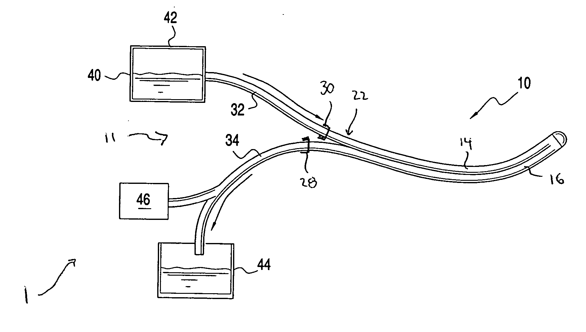
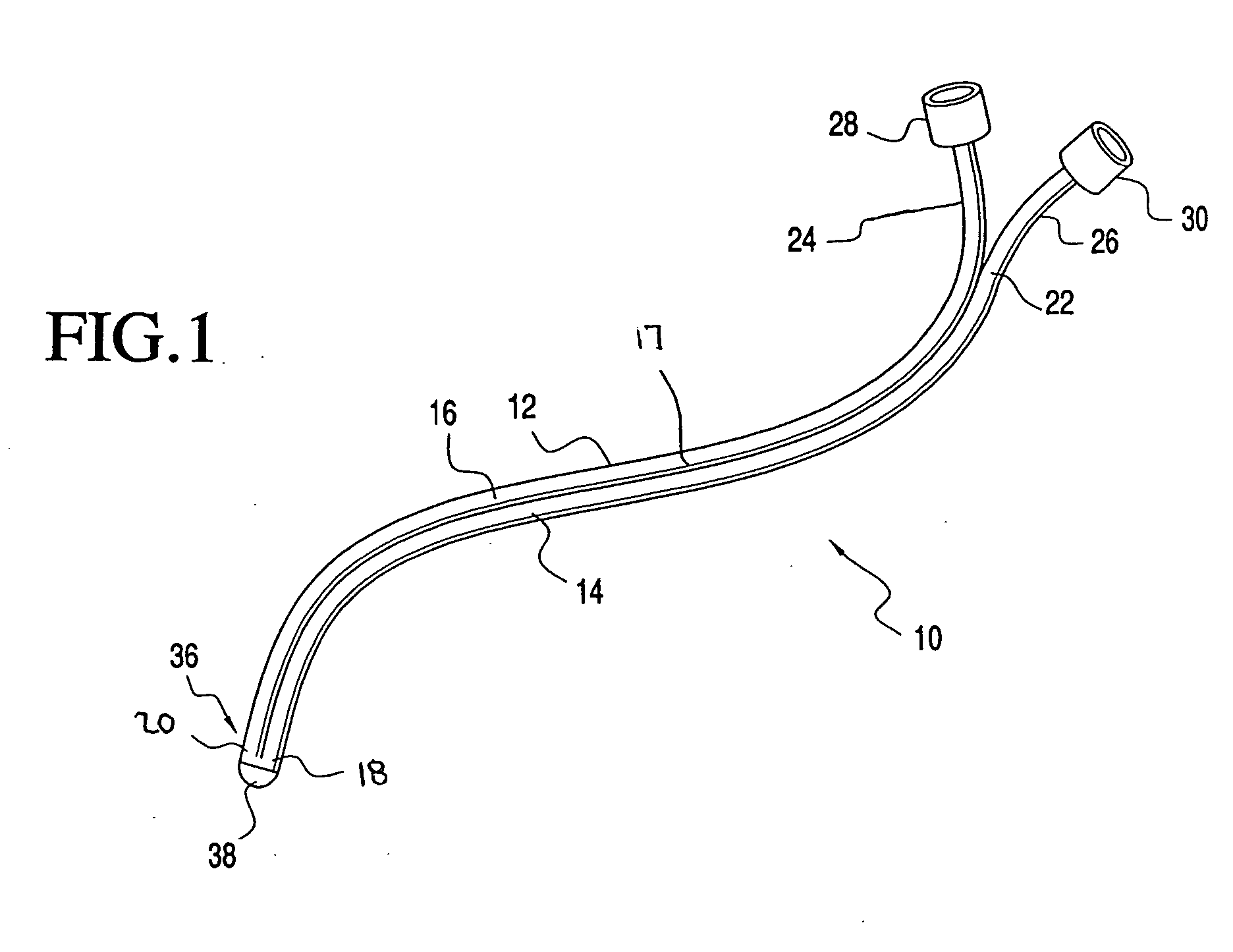
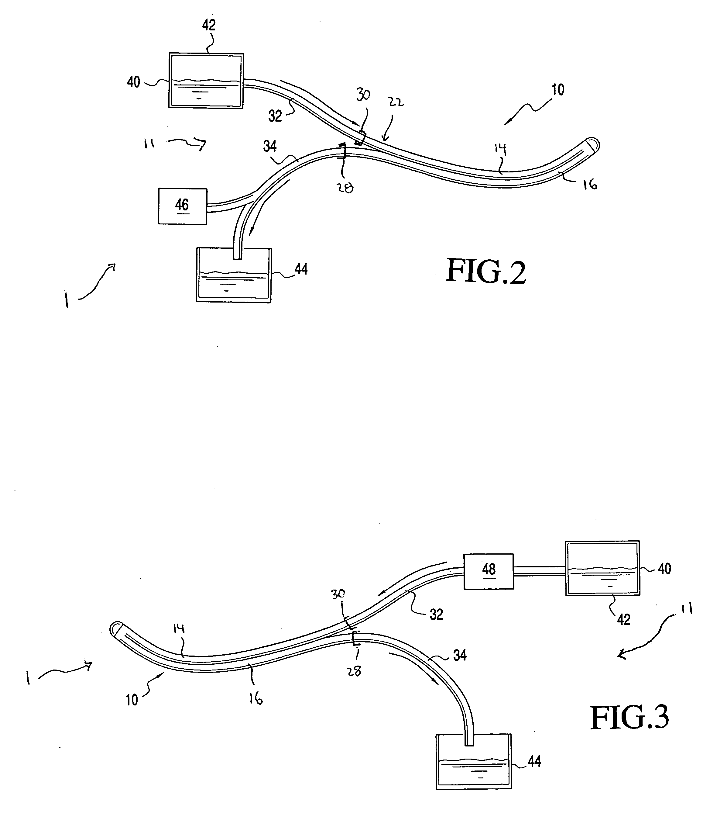
[0025] With reference to FIGS. 1 to 6, a method and apparatus for intra-thecal cooling is disclosed. The method and apparatus provide an effective mechanism for cooling the spinal cord in an effort to reduce the spinal ischemia. Generally, the present intra-thecal cooling catheter system 1 includes a closed-loop, cooling catheter 10 coupled to a cooling system 11 coupled to the catheter 10.

[0026] With regard to the intra-thecal cooling catheter 10 of the present invention, it is generally a dual lumen polyurethane catheter with a 50 / 50 split. That is, the cathe...


PUM


Abstract

A method for cooling of the brain includes the steps of positioning a cooling catheter within a ventricular cavity of the brain, the catheter including an inlet channel and outlet channel providing for the closed flow of cooling fluid into and out of the catheter, and cooling the catheter and ventricular cavity through the closed flow of cooling fluid through the catheter. An alternate method for cooling of the brain including the steps of positioning a cooling catheter within a spinal canal, the catheter including an inlet channel and outlet channel providing for the closed flow of cooling fluid into and out of the catheter, and cooling the catheter and brain through the closed flow of cooling fluid through the catheter.

Description

CROSS REFERENCE TO RELATED APPLICATIONS [0001] This application is a continuation-in-part of U.S. patent application Ser. No. 11 / 052,479, entitled “INTRA-THECAL CATHETER AND METHOD FOR COOLING THE SPINAL CORD”, filed Feb. 8, 2005, which is currently pending.BACKGROUND OF THE INVENTION [0002] 1. Field of the Invention [0003] The present invention relates to a method and apparatus for cooling the spinal cord and the brain. In particular, the invention relates to a method and apparatus for cooling of the spinal cord for descending and thoracoabdominal aortic surgery through the utilization of an intra-thecal catheter. [0004] 2. Description of the Prior Art [0005] Despite advances in spinal cord protection, paraplegia continues to be a serious complication of descending and thoracoabdominal aortic operations. Paraplegia has been a serious and vexing problem since the advent of direct thoracic aortic surgery some 40 years ago. Paraplegia continues to devastate the lives of patients under...

Claims


Application Information

Patent Timeline
Patent Type & Authority Applications(United States)
IPC IPC(8): A61F7/00
CPCA61F7/12G01D5/34A61F2007/126A61F2007/0056
Inventor ELEFTERIADES, JOHN
Owner ELEFTERIADES JOHN
Learn More