Signal-carrying flexure structure for micro-electromechanical devices

a micro-electromechanical and signal-carrying technology, applied in the direction of generators/motors, acceleration measurement using interia forces, instruments, etc., can solve the problems of power dissipation and thermal management, power loss and other problems of signal-carrying mem flexure, and achieve the effect of small spring constant and low resistan

Inactive Publication Date: 2007-03-01
TELEDYNE SCI & IMAGING
View PDF4 Cites 0 Cited by
  • Summary
  • Abstract
  • Description
  • Claims
  • Application Information

AI Technical Summary

Benefits of technology

[0007] A signal-carrying flexure structure for MEM devices is presented which overcomes the problems noted above, by providing a flexure which offers both a small spring constant and low resistance.

Problems solved by technology

Unfortunately, there is an inherent conflict between the mechanical and electrical requirements of a signal-carrying MEM flexure.
A high flexure resistance can give rise to power dissipation and thermal management problems, and lower Q and self-resonance issues if used in RF applications.
A flexure's ability to accommodate a desired current density (current / area), which is a particularly important parameter in MEM current sensor applications, is also likely to be compromised with a high resistance / small spring constant flexure.

Method used


Image

  • Signal-carrying flexure structure for micro-electromechanical devices
  • Signal-carrying flexure structure for micro-electromechanical devices
  • Signal-carrying flexure structure for micro-electromechanical devices

Examples


Embodiment Construction

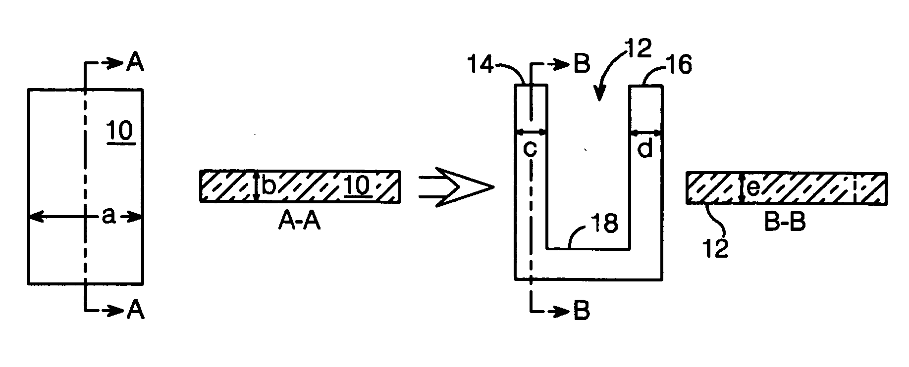
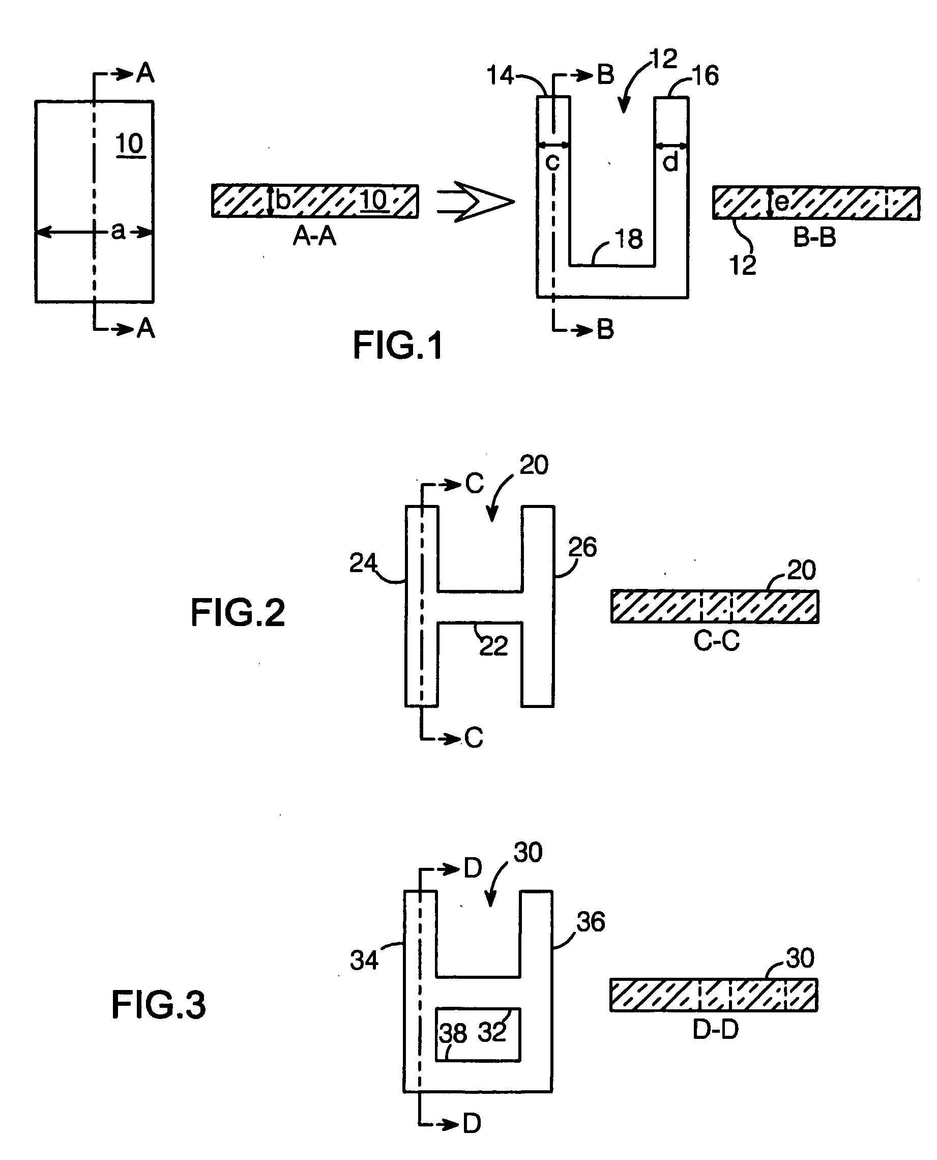
[0019] The basic principles of the present MEM signal-carrying flexure structure are illustrated in FIG. 1, which includes a plan and sectional view (cut along section line A-A) of a conventional solid flexure 10, and a plan and sectional view (cut along section line B-B) of a flexure structure 12 per the present invention. As used herein, a flexure is a flexible member, with beams being the most commonly-used type of flexure in MEM devices. Flexure 10 and flexure structure 12 have associated spring constant and resistance parameters. The spring constant of a free standing flexure is proportional to the flexure's width to the third power; i.e., k α a3*b, where a is flexure width and b is flexure height. Resistance and inductance, on the other hand, are linearly proportional to the inverse of flexure width; i.e., R,L α 1 / (a*b).

[0020] A signal-carrying flexure structure per the present invention is constructed from multiple, narrow flexure segments which are coupled together to form ...


PUM


Abstract

A signal-carrying flexure structure for a MEM device comprises at least two conductive flexure segments having respective cross-sectional areas, and at least one crosspiece affixed to the flexure segments to operatively couple the segments together such that the flexure segments and crosspiece form a single flexure structure. The resulting flexure structure's spring constant is less than that of a solid flexure having a comparable total cross-sectional area, while its resistance is approximately equal to that of the solid flexure.

Description

BACKGROUND OF THE INVENTION [0001] 1. Field of the Invention [0002] This invention relates to the field of micro-electromechanical devices, and particularly to the structure and spring constants of conductive flexures for such devices. [0003] 2. Description of the Related Art [0004] Micro-electromechanical (MEM) devices rely on the motion of one or more micro-machined flexures for their operation. For example, a flexure—typically a beam—may be made to move with respect to a fixed plate or another movable flexure to create a tunable capacitor. A switch may be provided with a flexure fixed at one end and free-floating at the other end, which is actuated by forcing the free end to move towards a substrate. [0005] Some MEM devices require that their movable flexure or flexures be conductive. For example, the operation of a MEM tunable capacitor or current sensor, as described, for example, in U.S. Pat. No. 5,959,516 to Chang et al. and U.S. Pat. No. 6,188,322 to Yao et al., requires the...

Claims


Application Information

Patent Timeline
Patent Type & Authority Applications(United States)
IPC IPC(8): H02N1/00H02K5/00
CPCH02N1/006
Inventor YAO, JUN J.
Owner TELEDYNE SCI & IMAGING
Why Eureka
Try Eureka