Solenoid valve

A solenoid valve, electromagnetic technology, applied in the direction of electromagnets, magnets, electromagnets with armatures, etc., can solve the problems of small space for setting the return spring and few effective turns, and achieve the effect of suppressing deviation and improving action stability.

Inactive Publication Date: 2022-03-01
SMC CORP
View PDF3 Cites 0 Cited by
  • Summary
  • Abstract
  • Description
  • Claims
  • Application Information

AI Technical Summary

Problems solved by technology

[0006] However, the solenoid valves disclosed in the above-mentioned Patent Documents 2 and 3 have to use a return spring with a short length, that is, a return spring with a small number of effective turns and a large spring constant because the installation space of the return spring formed by the above-mentioned dimple is small. Has the same problem as the solenoid valve described in Patent Document 1 above

Method used


Image

  • Solenoid valve
  • Solenoid valve
  • Solenoid valve

Examples


Embodiment Construction

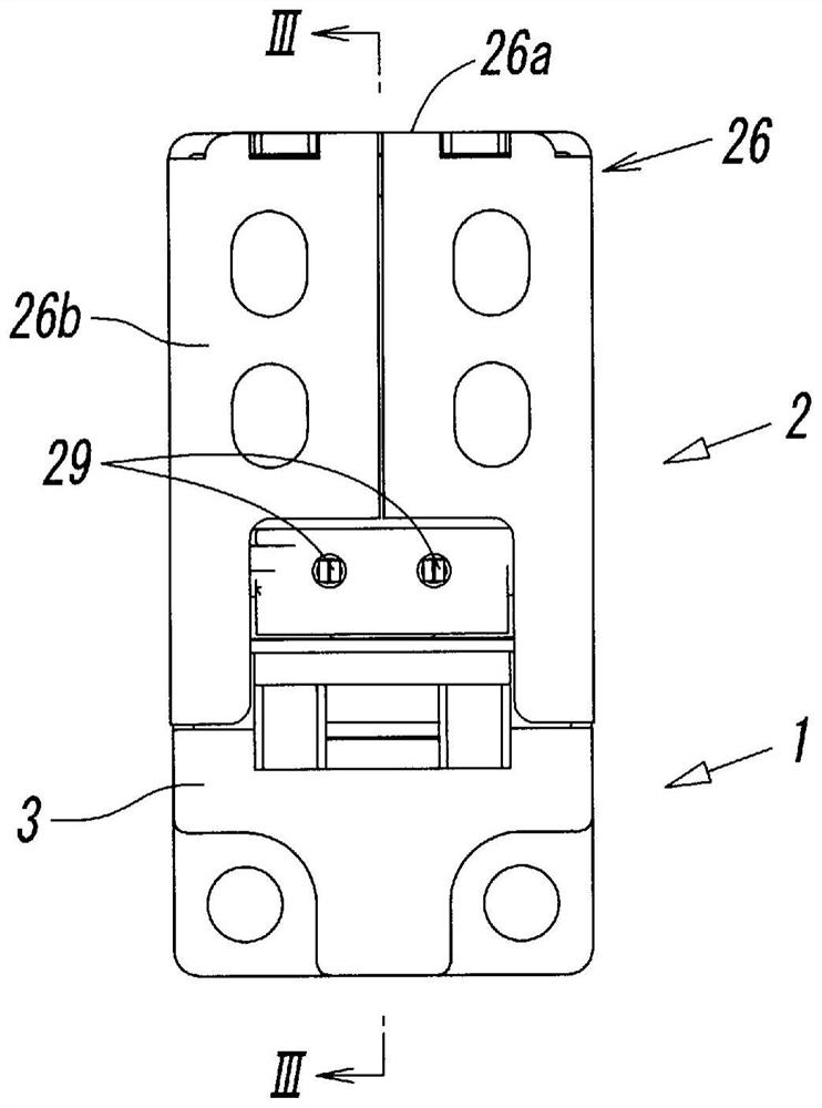
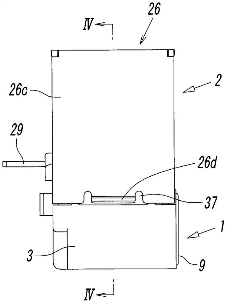
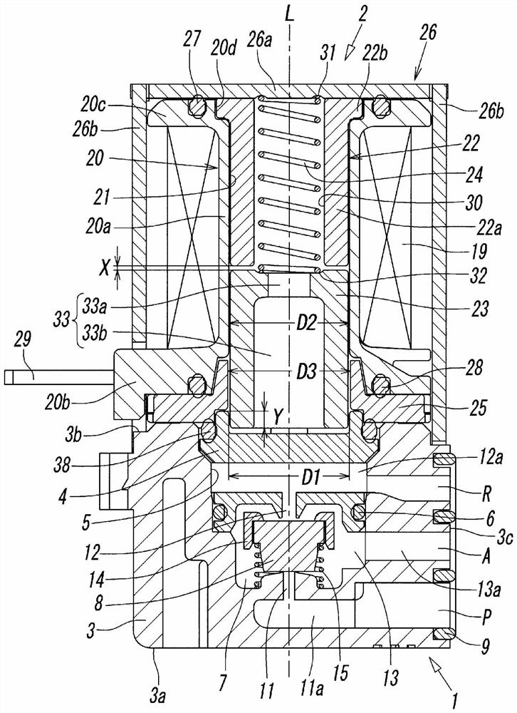
[0028] Figure 1-Figure 4 The solenoid valve shown is a three-port valve and has: a main valve part 1 having a valve member 8 for switching a fluid flow path; The electromagnetic operation parts 2 are connected in series along the axis L. As shown in FIG. The aforementioned axis L is an axis passing through the center of the bobbin hole 21 formed in the center of the bobbin 20 .

[0029] In addition, in the following description, the "proximal end" of each member forming the above-mentioned solenoid valve means figure 1 and figure 2 The end of the upper side, the "end" of each of the above components refers to figure 1 and figure 2 the end of the lower side.

[0030] The main valve unit 1 has a valve body 3 made of a non-magnetic material and a throttle 4 made of a non-magnetic material attached to the valve body 3 .

[0031] The valve body 3 has a rectangular block shape and has a first end (tip) 3a in the direction of the axis L and a second end (base end) 3b on the ...


PUM


Abstract

Provided is a solenoid valve using a return spring having a large number of effective turns and a small spring constant. An electromagnetic operating part (2) of an electromagnetic valve is provided with: a bobbin (20) around which a coil (19) is wound; a fixed iron core (22) and a movable iron core (23) which are accommodated in a bobbin hole (21) of the bobbin (20); a return spring (24) for returning the movable iron core (23) to an initial position; a magnetic cover (26) that covers the electromagnetic operation unit (2); and a magnetic plate (25) that magnetically couples the magnetic cover (26) and the movable iron core (23), a spring housing hole (30) is formed inside the fixed iron core (22) so as to penetrate the fixed iron core (22), the return spring (24) is housed inside the spring housing hole (30), the base end of the return spring (24) is in contact with the magnetic cover (26), and the magnetic plate (25) is in contact with the return spring (24). The tail end of the return spring (24) abuts against the movable iron core (23).

Description

technical field [0001] The present invention relates to a solenoid valve including a main valve unit having a valve member for switching a flow path, and an electromagnetic operation unit for switching the valve member. Background technique [0002] As disclosed in Patent Document 1, there is known a solenoid valve including a main valve unit having a valve member for channel switching and an electromagnetic operation unit for switching and operating the valve member. The electromagnetic operation part of the solenoid valve has: a hollow bobbin wound with a coil; a fixed iron core fixed in the center hole of the bobbin; and a movable iron core freely displaceable accommodated in the center hole. ; and a return spring that returns the movable iron core to the initial position. In addition, when the coil is energized, the movable iron core is attracted by the fixed iron core by the magnetic force generated on the fixed iron core, and when the power supply to the coil is cut o...

Claims


Application Information

Patent Timeline
Patent Type & Authority Applications(China)
IPC IPC(8): F16K31/06F16K1/00F16K1/32F16K27/02H01F7/16H01F7/14
CPCF16K31/0675F16K31/0655F16K1/00F16K1/32F16K27/029H01F7/16H01F7/14H01F7/081H01F7/1607F16K31/0627F16K27/0263F16K27/003
Inventor 高田芳行芳村亲一三田峰彦梅田和宽
Owner SMC CORP
Why Eureka
Try Eureka